
Fixing roller, and fixing device and image forming apparatus incorporating same

a fixing device and fixing roller technology, applied in the direction of electrographic process equipment, instruments, optics, etc., can solve the problems of increasing the repulsive load applied to the center of the fixing roller, increasing the repulsive load applied to the fixing roller, and reducing the recording medium

Active Publication Date: 2012-04-19
RICOH KK
View PDF2 Cites 66 Cited by
  • Summary
  • Abstract
  • Description
  • Claims
  • Application Information

AI Technical Summary

Benefits of technology

[0011]At least one embodiment may provide a fixing roller that includes a fixing sleeve including a heat generating layer; and a support roll inserted into the fixing sleeve to support the fixing sleeve and including a foam layer constituting an outer circumferential surface of the support roll. The foam layer includes recesses exposing pores containing air; and non-recessed portions contiguous to the recesses and adhered to an inner circumferential surface of the fixing sleeve.

Problems solved by technology

However, such configuration of the fixing roller has a drawback in that as the induction heater heats the fixing roller, air trapped between the outer circumferential surface of the support roll and the inner circumferential surface of the fixing sleeve thermally expands and cannot be exhausted from the fixing roller, increasing repulsive load, that is, pressure generated by the pressing roller pressing against the fixing roller, applied at the center of the fixing roller in the axial direction thereof.
As a result, the fixing roller with the increased repulsive load may crease the recording medium that contacts the fixing roller as the recording medium passes through the nip formed between the fixing roller and the pressing roller.
However, as the induction heater heats the fixing roller, air trapped between the fixing sleeve and the support roll thermally expands, increasing the repulsive load applied to the center of the fixing roller in the axial direction thereof as shown in graph B2.

Method used


Image

  • Fixing roller, and fixing device and image forming apparatus incorporating same
  • Fixing roller, and fixing device and image forming apparatus incorporating same
  • Fixing roller, and fixing device and image forming apparatus incorporating same

Examples


Embodiment Construction

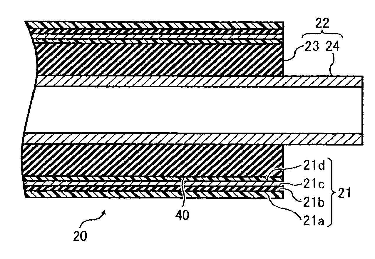
[0026]It will be understood that if an element or layer is referred to as being “on”, “against”, “connected to”, or “coupled to” another element or layer, then it can be directly on, against, connected or coupled to the other element or layer, or intervening elements or layers may be present. In contrast, if an element is referred to as being “directly on”, “directly connected to”, or “directly coupled to” another element or layer, then there are no intervening elements or layers present. Like numbers refer to like elements throughout. As used herein, the term “and / or” includes any and all combinations of one or more of the associated listed items.

[0027]Spatially relative terms, such as “beneath”, “below”, “lower”, “above”, “upper”, and the like, may be used herein for ease of description to describe one element or feature's relationship to another element(s) or feature(s) as illustrated in the figures. It will be understood that the spatially relative terms are intended to encompas...


PUM


Abstract

A fixing roller includes a fixing sleeve including a heat generating layer; and a support roll inserted into the fixing sleeve to support the fixing sleeve and including a foam layer constituting an outer circumferential surface of the support roll. The foam layer includes recesses exposing pores containing air; and non-recessed portions contiguous to the recesses and adhered to an inner circumferential surface of the fixing sleeve.

Description

CROSS-REFERENCE TO RELATED APPLICATIONS[0001]This patent application is based on and claims priority pursuant to 35 U.S.C. §119 to Japanese Patent Application No. 2010-234518, filed on Oct. 19, 2010, in the Japan Patent Office, the entire disclosure of which is hereby incorporated herein by reference.FIELD OF THE INVENTION[0002]Example embodiments generally relate to a fixing roller, a fixing device, and an image forming apparatus, and more particularly, to a fixing roller for heating a recording medium to fix a toner image thereon, and a fixing device and an image forming apparatus including the fixing roller.BACKGROUND OF THE INVENTION[0003]Related-art image forming apparatuses, such as copiers, facsimile machines, printers, or multifunction printers having at least one of copying, printing, scanning, and facsimile functions, typically form an image on a recording medium according to image data. Thus, for example, a charger uniformly charges a surface of an image carrier; an optic...

Claims


Application Information

Patent Timeline
IPC IPC(8): G03G15/20
CPCG03G15/2057
Inventor OGAWA, TADASHIUCHITANI, TAKESHIUENO, SATOSHIHASE, TAKAMASAKAWATA, TEPPEISAITO, KAZUYAYUASA, SHUUTAROHYAMAJI, KENSUKE
Owner RICOH KK
Features
  • Generate Ideas
  • Intellectual Property
  • Life Sciences
  • Materials
  • Tech Scout
  • Unparalleled Data Quality
  • Higher Quality Content
  • 60% Fewer Hallucinations
Learn More