Structure for mounting camera on vehicle

a technology for mounting structures and cameras, applied in the direction of camera body details, instruments, stands/trestles, etc., can solve the problems of inconvenient attachment/detachment of cameras to/from vehicles, and achieve the effects of convenient attachment/detachment, simple structure, and easy adjustmen

Active Publication Date: 2012-04-26
HONDA ELESYS CO LTD +1
View PDF6 Cites 42 Cited by
  • Summary
  • Abstract
  • Description
  • Claims
  • Application Information

AI Technical Summary

Benefits of technology

The present invention provides a structure for mounting a camera on a vehicle using a slide mechanism. The structure includes a base fixed to the vehicle body, a camera, and a spring member that generates a pressing force in a direction perpendicular to the sliding direction between the base and the camera to hold the camera on the base. The spring member includes an S-shaped spring portion attached to the camera, which allows for easy attachment and detachment of the camera. The base includes sliding guide portions and slide concave portions, and the slide mechanism is formed of the sliding guide portions and the slide concave portions, which simplifies the attachment of the camera onto the base. The spring member can be attached to the camera at a side of the first spring plate portion or between the left and right slide walls of the camera, and the external appearance of the camera can be improved by surrounding the spring member.

Problems solved by technology

When the camera is fixed by bolts, the attaching / detaching of the camera to / from the vehicle is inconvenient.

Method used


Image

  • Structure for mounting camera on vehicle
  • Structure for mounting camera on vehicle
  • Structure for mounting camera on vehicle

Examples


first embodiment

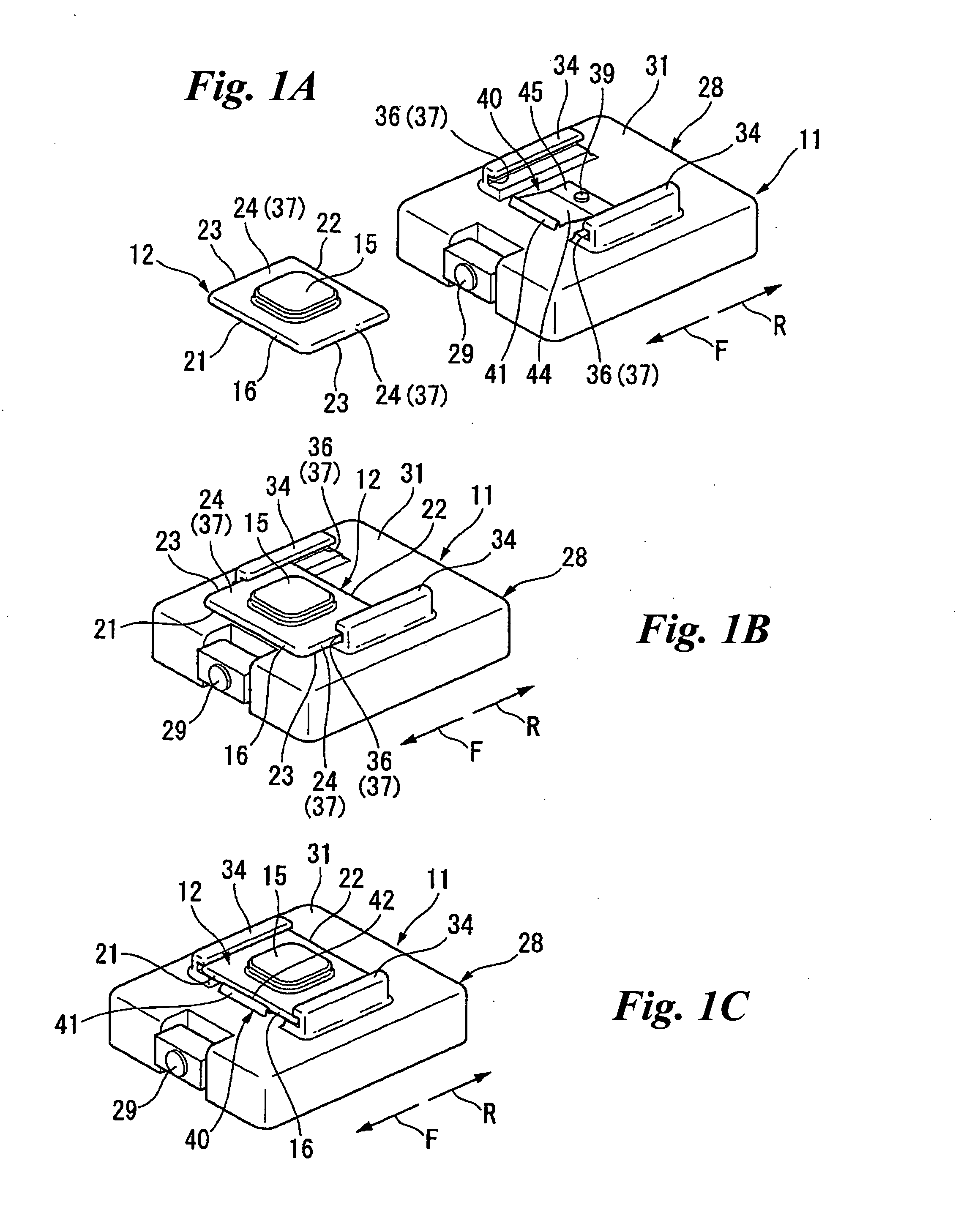
[0030]A structure for mounting a camera on a vehicle is described with reference to FIGS. 1A to 11.

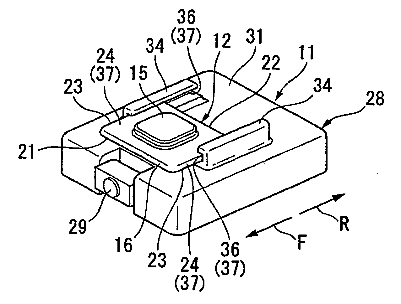
[0031]In the drawings, a camera 11 and a base 12 for mounting the camera 11 on a vehicle are illustrated. As shown in FIGS. 1A to 1C, the camera 11 is slidable with respect to the base 12 to be attached / detached to / from the base 12.

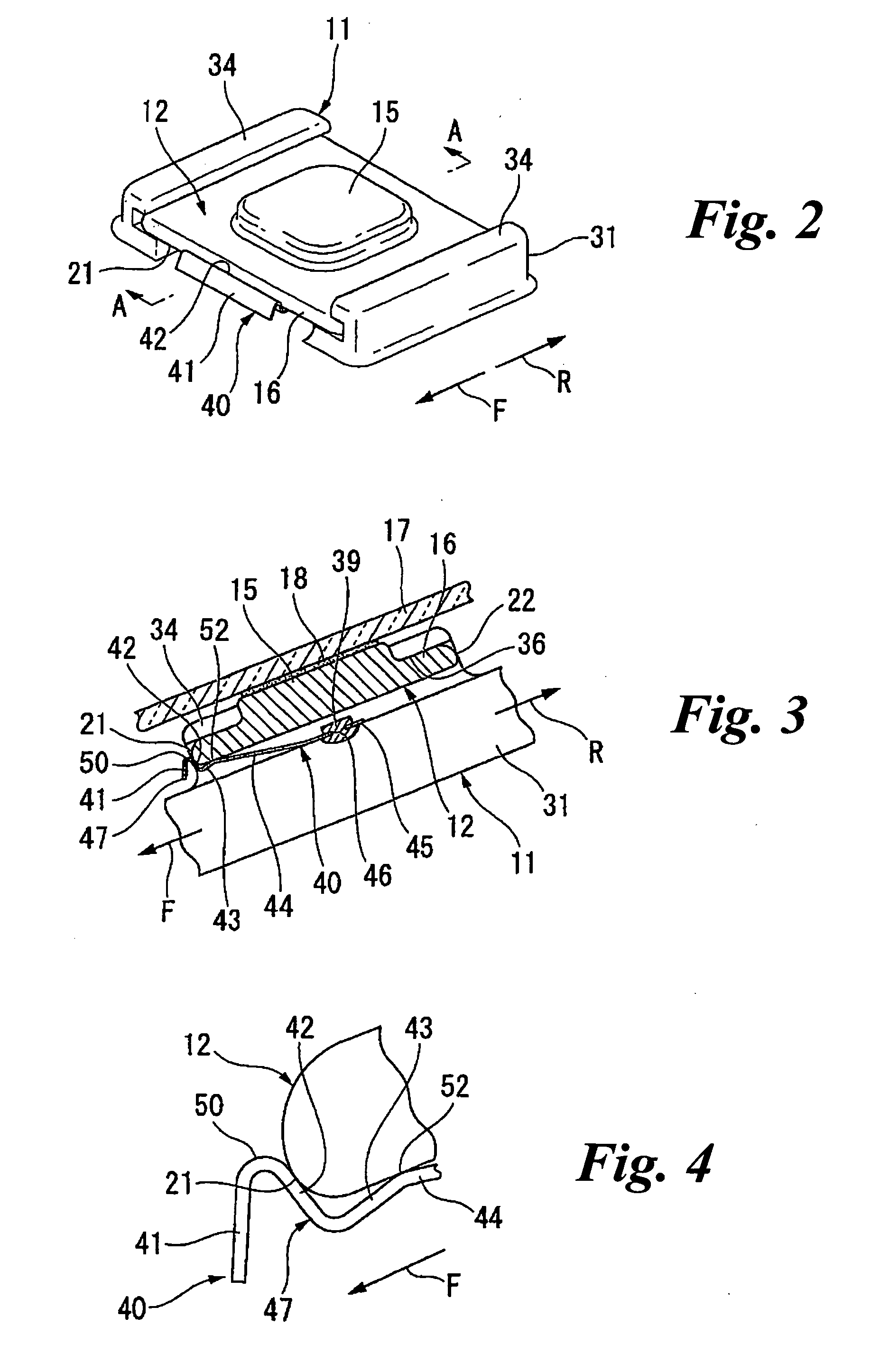
[0032]The base 12 includes an attachment portion 15 and a guide plate portion 16. The attachment portion 15 is an approximately rectangular plate having a low height. The guide plate portion 16 is a rectangular plate extends from the bottom of the attachment portion 15 in four directions. The attachment portion 15 and the guide plate 16 of the base 12 are integrally formed, for example, by a metal casting. Generally, the vehicle has a front glass 17 inclining toward the forward and downward direction. As shown in FIG. 3, the top surface of the attachment portion 15 is bonded to the front grass 17 by a double-sided adhesive sheet 18 to thereby attach the bas...

second embodiment

[0057]In the second embodiment, as shown in FIG. 12, a spring member 60 has an attachment plate portion 61 and first to fourth spring plate portions 61 to 65. The attachment plate portion 61 extends in the camera-mounting direction (F). The first spring plate portion 62 extends from a rear end of the attachment plate portion 61, and inclines toward the rearward and upward direction with respect to the attachment plate portion 61. The second spring plate portion 63 extends from a rear end of the first spring plate portion 62, and inclines toward the rearward and downward direction with respect to the first spring plate portion 62. The third spring plate portion 64 extends from a rear end of the second spring plate portion 63, and inclines toward the rearward and upward direction with respect to the second spring plate portion 63. The fourth spring plate portion 65 extends from a rear end of the third spring plate portion 64, and inclines toward the rearward and downward direction wit...


PUM


Abstract

According to one embodiment, there is provided a structure for mounting a camera on a vehicle, including: a base fixed to a vehicle body; a camera; a slide mechanism configured to allow the camera to slide in a sliding direction so as to be detachably engaged with the base; and a spring member configured to generate a pressing force in a direction perpendicular to the sliding direction between the base and the camera in an engaged state, thereby holding the camera with respect to the base.

Description

CROSS-REFERENCE TO RELATED APPLICATION(S)[0001]This application claims priority from Japanese Patent Application No. 2010-239072 filed on Oct. 25, 2010, the entire contents of which are incorporated herein by reference.FIELD[0002]The embodiments described herein relate generally to a structure for mounting a camera on a vehicle.BACKGROUND[0003]A camera is mounted on a vehicle to capture images outside the vehicle. For example, the camera is used as a part of a drive recorder that records a front image of the vehicle. For example, in JP-2010-195235-A, to mount the camera on the vehicle, an attachment portion is fixed to a front glass of the vehicle using a double-sided tape, and then, the camera is fixed to the attachment portion using bolts.[0004]When the camera is fixed by bolts, the attaching / detaching of the camera to / from the vehicle is inconvenient.SUMMARY[0005]According to a first aspect of the present invention, there is provided a structure for mounting a camera on a vehicle...

Claims


Application Information

Patent Timeline
Patent Type & Authority Applications(United States)
IPC IPC(8): G03B17/56
CPCB60R11/04G03B17/566G03B17/561F16M11/041
Inventor ONISHI, MOTOYASUMATORI, TADAHIRO
Owner HONDA ELESYS CO LTD
Why Eureka
Try Eureka