Supercharge Your Innovation With Domain-Expert AI Agents!

Computer system for automatically classifying roof elements

a computer system and roof element technology, applied in computing, geometric cad, instruments, etc., can solve the problems of difficult to distinguish between two commercial properties, difficult to determine what it is they are looking at in the image, and expensive and potentially hazardous jobs for measuring an actual roo

Active Publication Date: 2012-04-26
PICTOMETRY INTERNATIONAL CORPORATION
View PDF1 Cites 35 Cited by
  • Summary
  • Abstract
  • Description
  • Claims
  • Application Information

AI Technical Summary

Benefits of technology

The present patent describes a set of instructions for identifying line segments of a roof and automatically classifying them as predefined roof elements using geo-referenced images. The set of instructions can be accessed on a computer system and can be used to create a three-dimensional model of the roof. The technical effects of this patent include improved efficiency in identifying and classifying roof elements, which can save time and reduce errors in roof inspections.

Problems solved by technology

As a result, many people have difficulty determining what it is they are looking at in the image.
For instance, they might have difficulty distinguishing between two commercial properties since the only thing they can see of the properties in the ortho-mosaic is their roof tops, where as most of the distinguishing properties are on the sides of the buildings.
In addition, because oblique images are not generally ortho-rectified, they are still in the natural appearance that the camera captures as opposed to the mathematical construction of the ortho image.
For roofing, this is even more important since measuring an actual roof can be a costly and potentially hazardous job—especially with steeply pitched roofs.
However, the prior software did not include any manner of automatically classifying roof elements, such as ridge lines, drip edges or eaves and the like so that reports including cumulative lengths of such roof elements could be automatically or semi-automatically prepared.

Method used


Image

  • Computer system for automatically classifying roof elements
  • Computer system for automatically classifying roof elements
  • Computer system for automatically classifying roof elements

Examples


Embodiment Construction

[0033]Before explaining at least one embodiment of the disclosure in detail, it is to be understood that the disclosure is not limited in its application to the details of construction, experiments, exemplary data, and / or the arrangement of the components set forth in the following description or illustrated in the drawings.

[0034]The disclosure is capable of other embodiments or of being practiced or carried out in various ways. Also, it is to be understood that the phraseology and terminology employed herein is for purpose of description and should not be regarded as limiting.

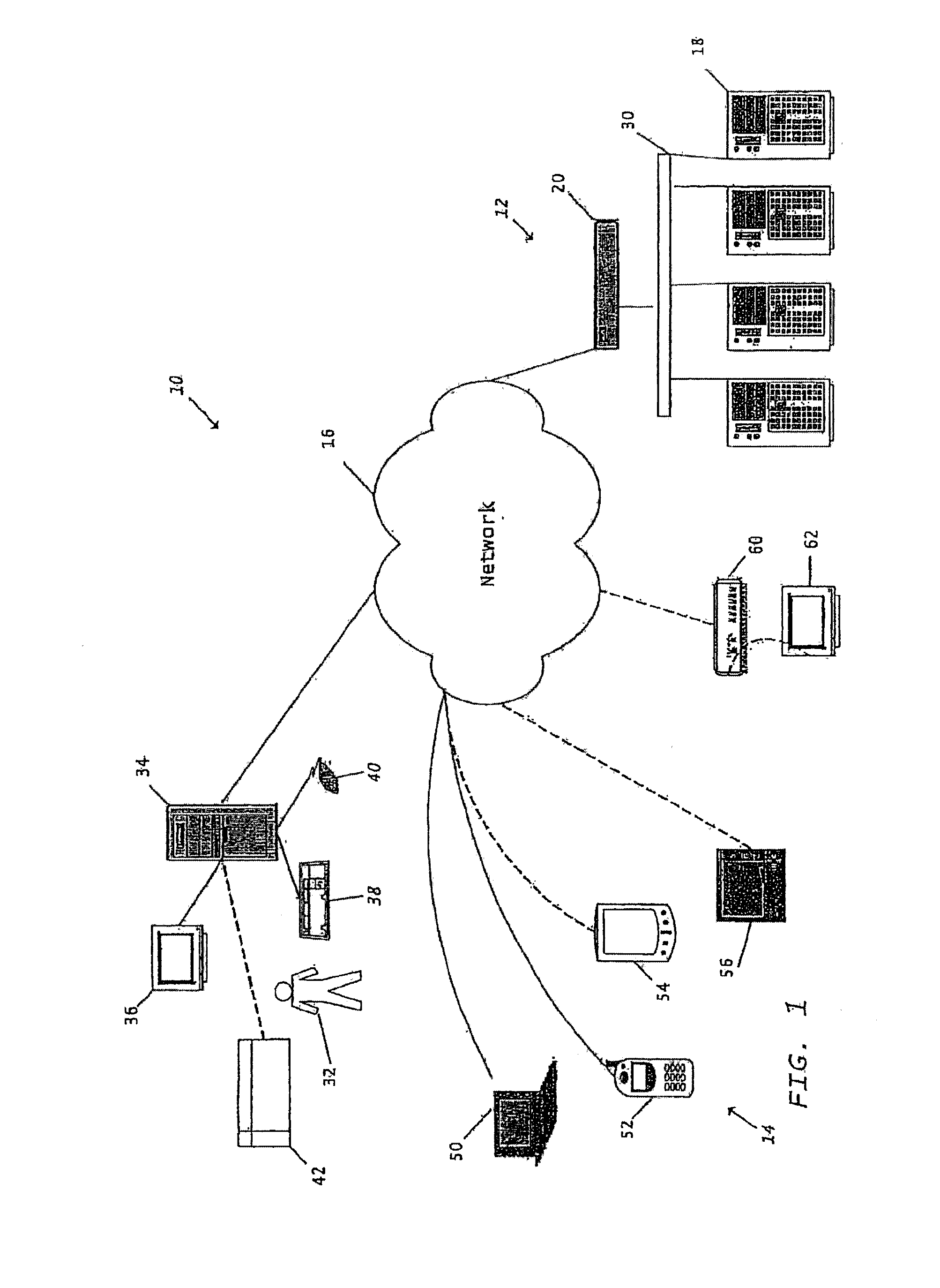
[0035]Referring now to the drawings, and in particular to FIG. 1, shown therein and designated by a reference numeral 10 is an exemplary computer system constructed in accordance with the present disclosure. The computer system 10 can be a system or systems that are able to embody and / or execute the logic of the processes described herein. The logic embodied in the form of software instructions, or firmware ma...


PUM


Abstract

A set of instructions stored on at least one computer readable medium for running on a computer system. The set of instructions includes instructions for identifying line segments of a roof that is preferably displayed within a geo-referenced image, instructions for determining three-dimensional information of the line segments including position, orientation and length of the line segments preferably utilizing the geo-referenced image, and instructions for classifying, automatically, at least one of the line segments as one of a plurality of predefined roof elements utilizing at least one of the relative position and orientation of the line segments.

Description

CROSS REFERENCE TO RELATED APPLICATIONS[0001]Not Applicable.FIELD OF INVENTION[0002]The presently claimed and disclosed invention(s) relate to methods and computer systems for generating information indicative of roofs of buildings using geo-referenced images. More particularly, the presently claimed and disclosed invention(s) use a methodology for automatically classifying line segments as one of a plurality of predefined roof elements utilizing at least one of a relative position and orientation of the line segments.BACKGROUND OF THE ART[0003]In the remote sensing / aerial imaging industry, imagery is used to capture views of a geographic area and to be able to measure objects and structures within the images as well as to be able to determine geographic locations of points within the image. These are generally referred to as “geo-referenced images” and come in two basic categories:[0004]Vertical Imagery—these images are captured with the camera pointed vertically downward and thus ...

Claims


Application Information

Patent Timeline
Patent Type & Authority Applications(United States)
IPC IPC(8): G06F17/50
CPCG06F17/5004G06F30/13
Inventor STEPHENS, JOHN WILLIAMGIUFRRIDA, FRANK D.SCHULTZ, STEPHEN L.ADAMS, STEVEWANG, YANDONG
Owner PICTOMETRY INTERNATIONAL CORPORATION
Features
  • R&D
  • Intellectual Property
  • Life Sciences
  • Materials
  • Tech Scout
  • Unparalleled Data Quality
  • Higher Quality Content
  • 60% Fewer Hallucinations
Learn More