Eureka AIR delivers breakthrough ideas for toughest innovation challenges, trusted by R&D personnel around the world.

Program for test case generation based on use case diagram and method for test case generation using the same

a test case and use case technology, applied in the field of test case generating programs, can solve the problems of deteriorating efficiency, degrading productivity, and degrading quality of test cases, and achieve the effect of reducing the cost of system development and effective testing

Active Publication Date: 2012-04-26
LEADPOINT SYST INC +1
View PDF0 Cites 11 Cited by
  • Summary
  • Abstract
  • Description
  • Claims
  • Application Information

AI Technical Summary

Benefits of technology

[0009]It is, therefore, an object of the present invention to provide a use case diagram-based test case generating program capable of sequentially displaying the process of generating a test case from a use case diagram and automating the test case generation process, by using a use case specification in which a procedure or method scenario of a function is specified in a use diagram, to thus allow a layman to easily generate a certain level of a test case, and a method for generating a test case by using the same.
[0020]In the program for generating a test case based on a use case diagram and the method for generating a test case using the same according to exemplary embodiments of the present invention, since a use case specification specifying a procedure or method scenario performed in a use case diagram is used to complement insufficient information of a use case diagram used to extract a test case, a layer, although he is not a specialist or an expert, can easily generate a certain level of a test case to effectively perform a test.

Problems solved by technology

If the test case is created by a layman, much time will be taken to generate the test case and the quality of the test case would be degraded.
As a result, because all the tasks must be manually performed, the efficiency deteriorates to degrade productivity.

Method used


Image

  • Program for test case generation based on use case diagram and method for test case generation using the same
  • Program for test case generation based on use case diagram and method for test case generation using the same
  • Program for test case generation based on use case diagram and method for test case generation using the same

Examples


Embodiment Construction

[0033]The foregoing and other objects, features, aspects and advantages of the program for generating a test case based on a use case diagram and a method for generating a test by using the same according to exemplary embodiments of the present invention will become more apparent from the following detailed description of the present invention when taken in conjunction with the accompanying drawings.

[0034]Program for Generating Test Case Based on Use Case Diagram

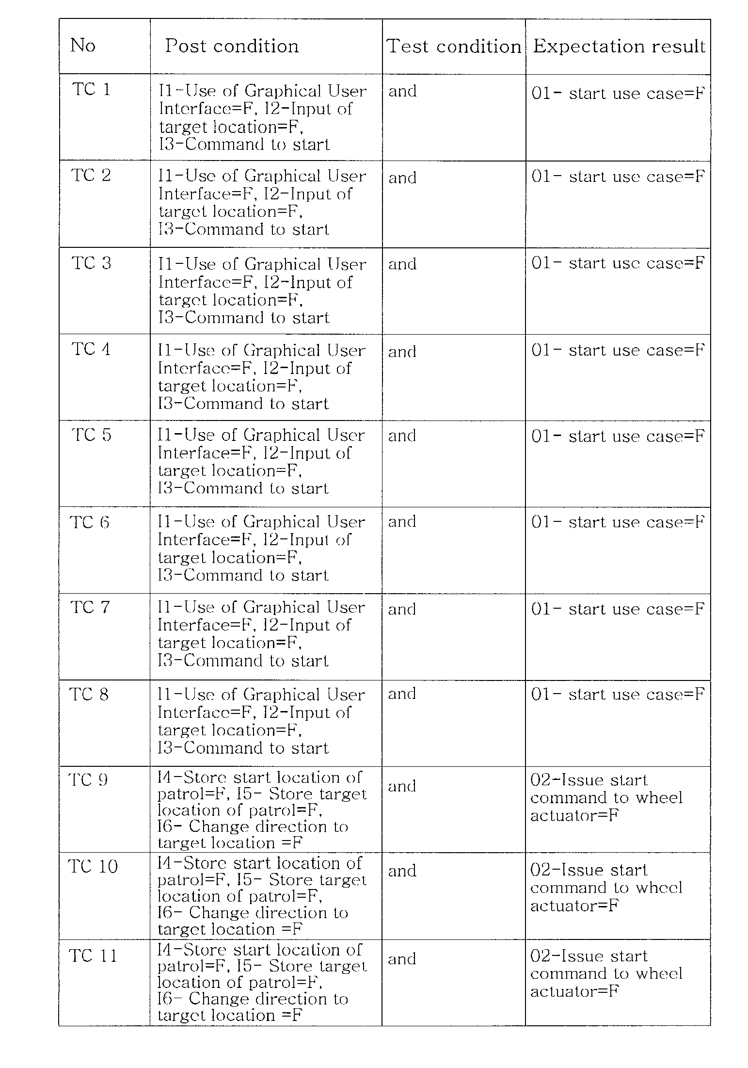
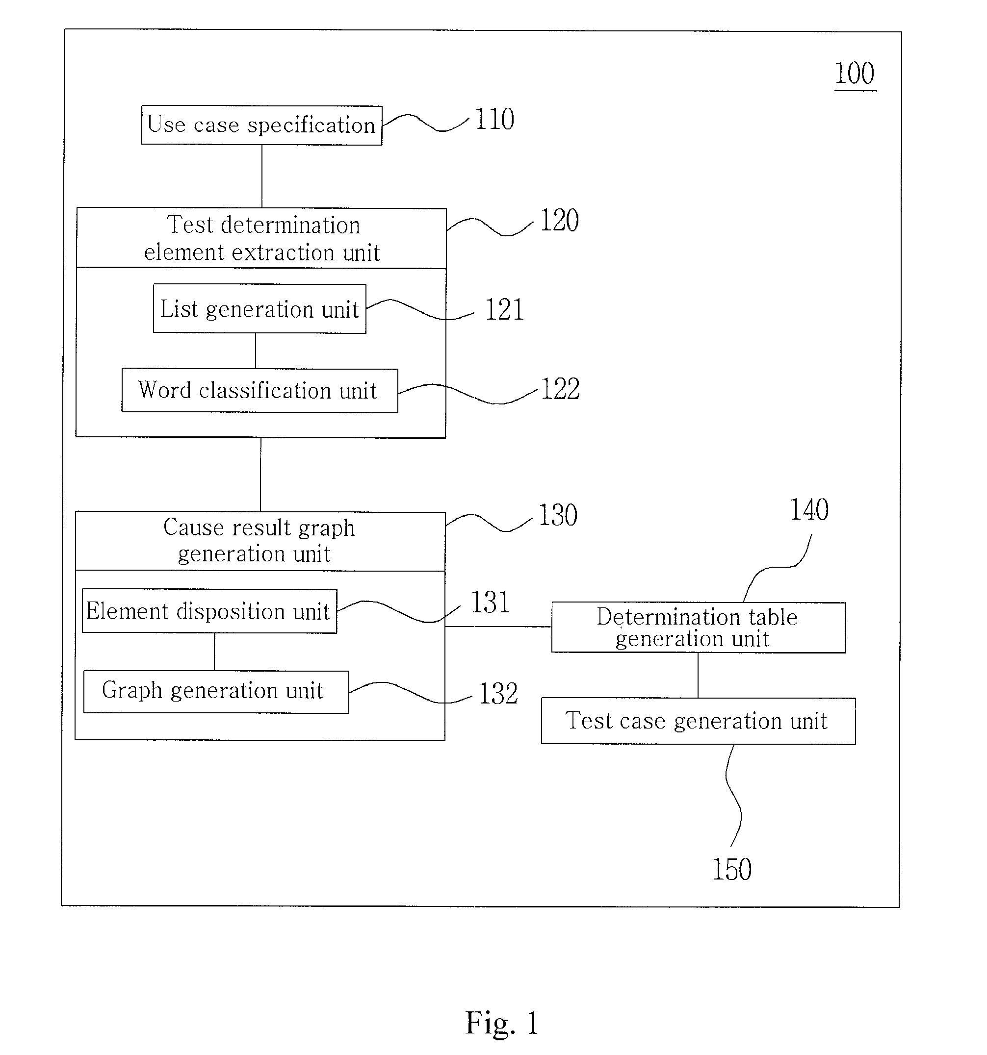
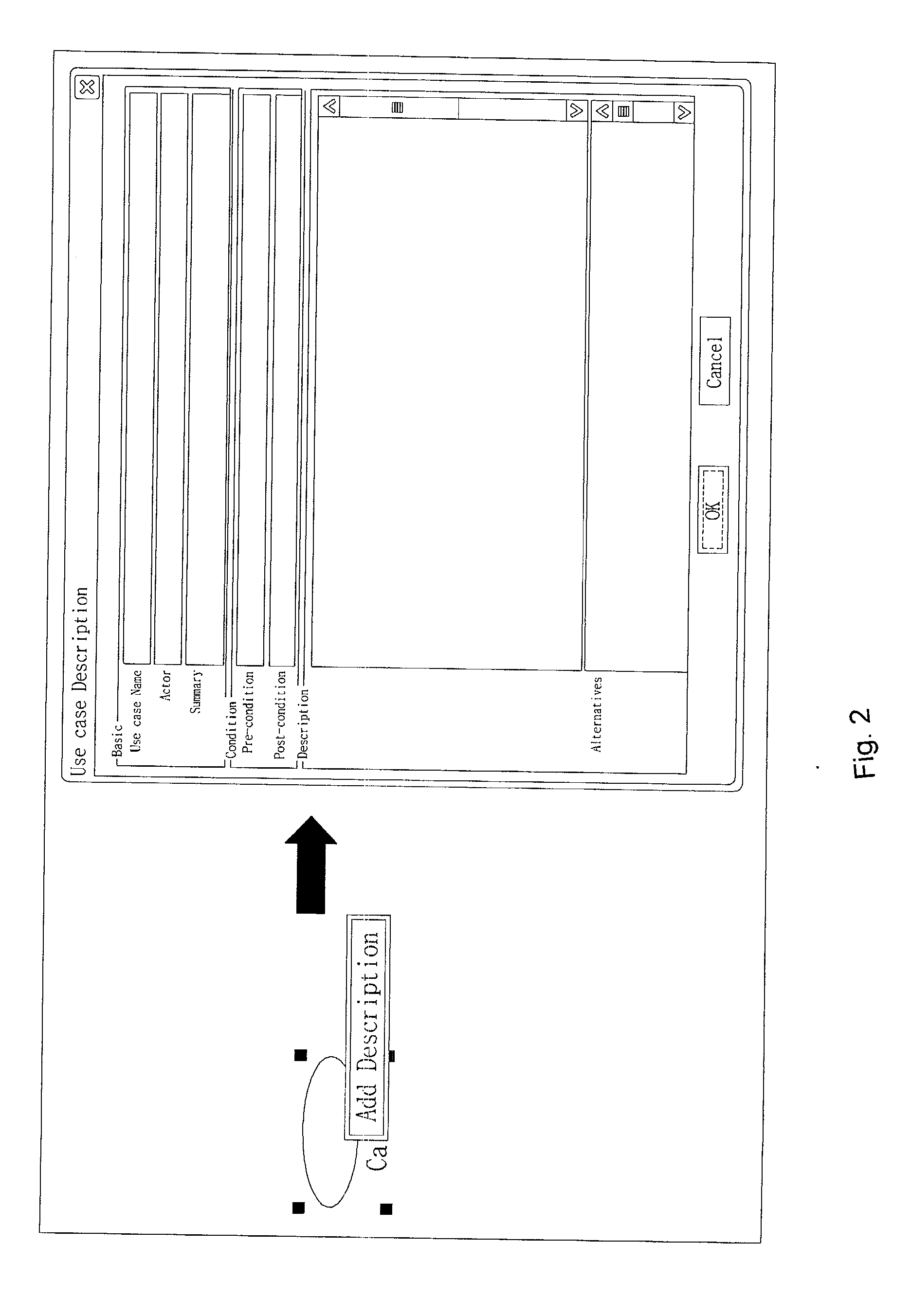
[0035]With reference to FIGS. 1 to 5, a test case generation program 100 based on a use case diagram according to an exemplary embodiment of the present invention may be configured to include a use case specification 110 specifying a procedure or method scenario performed in a use case diagram, a test determination element extraction unit 120 separating the scenario specified in the use case specification 110 according to the meaning of words to extract test determination elements, a cause result graph generation unit 130 ex...


PUM


Abstract

In the program for generating a test case based on a use case diagram and the method for generating a test case using the same according to exemplary embodiments of the present invention, since a use case specification specifying a procedure or method scenario performed in a use case diagram is used to complement insufficient information of a use case diagram used to extract a test case, a layer, although he is not a specialist or an expert, can easily generate a certain level of a test case to effectively perform a test. Thus, requirements can be verified in advance by generating a test case from a use case program, reducing the costs for a system development.

Description

[0001]The patent application claims the priority under 35 U.S.C. §119 of Korean Patent Application No. 10-2010-102376, filed on Oct. 20, 2010, the disclosure of which is incorporated by reference herein in its entirety.BACKGROUND OF THE INVENTION[0002]1. Field of the Invention[0003]The present invention relates to a program for generating a test case based on a use case diagram and a method for generating a test case using the same and, more particularly, to a use case diagram-based test case generating program capable of generating a test case by using a use case specification in which a procedure or method scenario in a use case diagram are specified, and a method for generating a test case by using the same.[0004]2. Related Art[0005]A use case diagram expresses functions (behaviors or actions) viewed from the exterior.[0006]Namely, the use case diagram allows for a user to know about (or recognize) which functions a system has when the system is viewed from the outside (i.e., vie...

Claims


Application Information

Patent Timeline
IPC IPC(8): G06N5/04
CPCG06F11/3684G06N5/04
Inventor KIM, WOOYEOLSON, HYUNSEUNGKIM, ROBERTYOUNGCHULJIN, SUCHUN
Owner LEADPOINT SYST INC
Why Eureka
Eureka Blog
Learn More