Supercharge Your Innovation With Domain-Expert AI Agents!

Separation module

a technology of separation module and separation module, which is applied in the direction of membrane technology, reverse osmosis, membrane technology, etc., can solve the problems of reducing purification, tearing in the membrane, and not being able to achieve robust implementation

Inactive Publication Date: 2012-05-03
GENERAL ELECTRIC CO
View PDF0 Cites 13 Cited by
  • Summary
  • Abstract
  • Description
  • Claims
  • Application Information

AI Technical Summary

Benefits of technology

[0008]A separation module utilizing a feed spacer and a method for forming such a separation module are provided. A gasket comprising a flexible waterproof material is disposed on at least part of one or more edges of the feed spacer. A membrane layer is disposed on a first surface of the feed spacer. A permeate carrier is disposed on a surface of the membrane element opposite the feed spacer.
[0009]Several embodiments of a separation module are provided. The membrane module includes at least one layer of a permeate carrier, at least one layer of a membrane element, and at least one layer of a feed spacer. The membrane module further includes at least one layer of a feed spacer wherein edges of the feed spacer are at least partly covered by one or more strips of a waterproof flexible material. A seal is formed between the membrane element and the feed spacer, wherein the one or more strips of the waterproof flexible material is compressed against the membrane element to form the seal. The flexible waterproof material may be compressed against the membrane element either by winding the membrane stack around a central core, or by compressing the flexible waterproof material against the membrane element using a suitable frame and plate assembly.

Problems solved by technology

Though channels defined by this method have been shown, a robust implementation has yet to be achieved.
When the feed channel is pressurized above the pressure of the permeate channel, a stress concentration at the membrane-adhesive joint develops and generally results in a tear in the membrane.
The tear in the membrane then results in decreased purification.
However, such joints may be susceptible to leaks at high pressures of the feed.
Further, processes involved in producing chemical joints may be expensive and time consuming.
Variations in the thickness of each feed channel along the flow direction may also not be possible in such cases.
The chemically joined edges may also cause damage to the layer of membrane element.
Moreover, chemical joints may not provide additional rigidity to the layer of permeate carrier.
In spiral wound modules, it may also be difficult to roll chemically joined leaves around the core.

Method used


Image

  • Separation module
  • Separation module
  • Separation module

Examples


Embodiment Construction

[0019]Various embodiments presented herein will be described in detail below with reference to accompanying drawings. It will be apparent, however, that these embodiments may be practiced without some or all of these specific details. In other instances, well known process steps or elements have not been described in detail in order not to unnecessarily obscure the description of the embodiments. The following example embodiments and their aspects are described and illustrated in conjunction with apparatuses, methods, and systems which are meant to be illustrative examples, not limiting in scope.

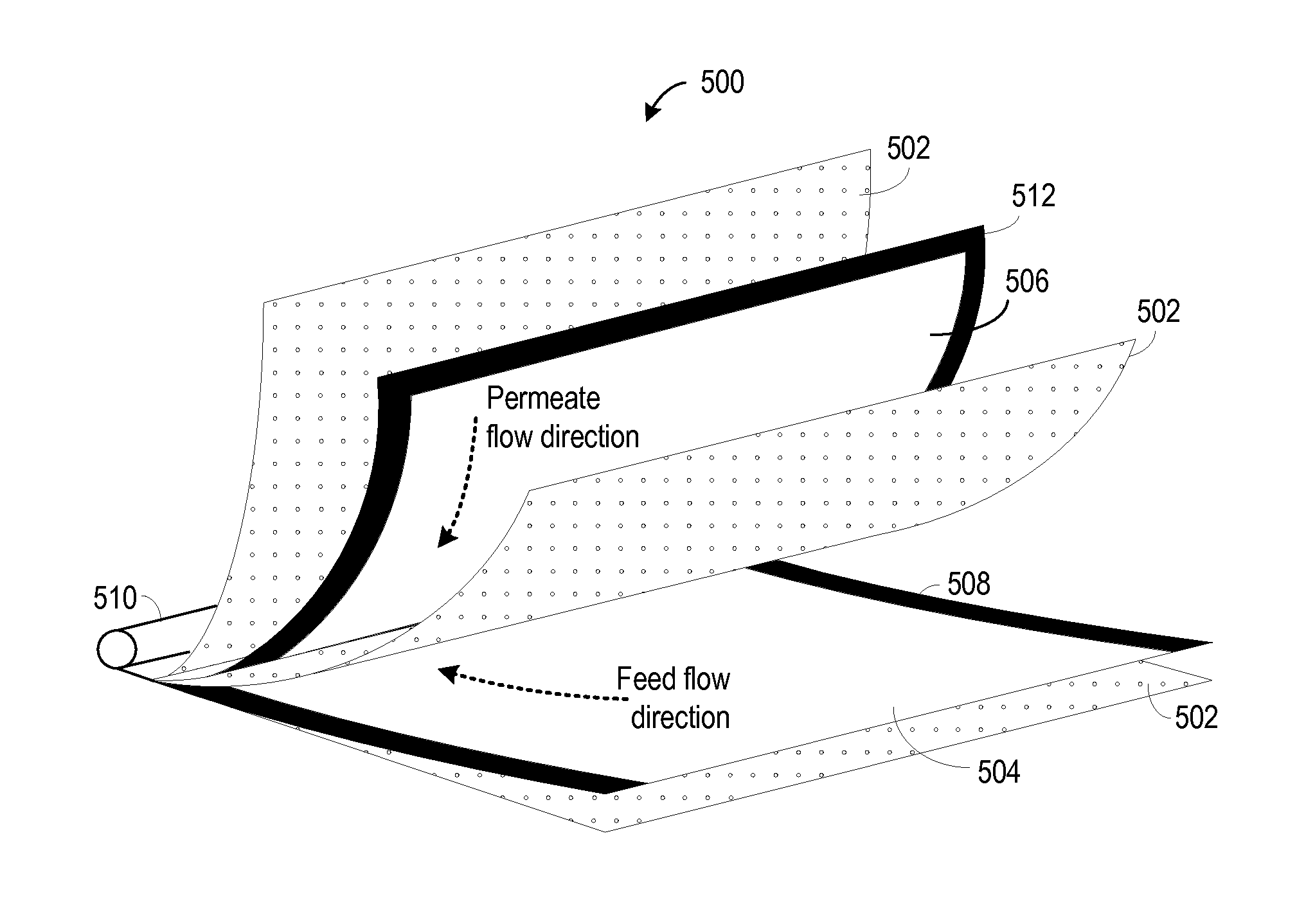
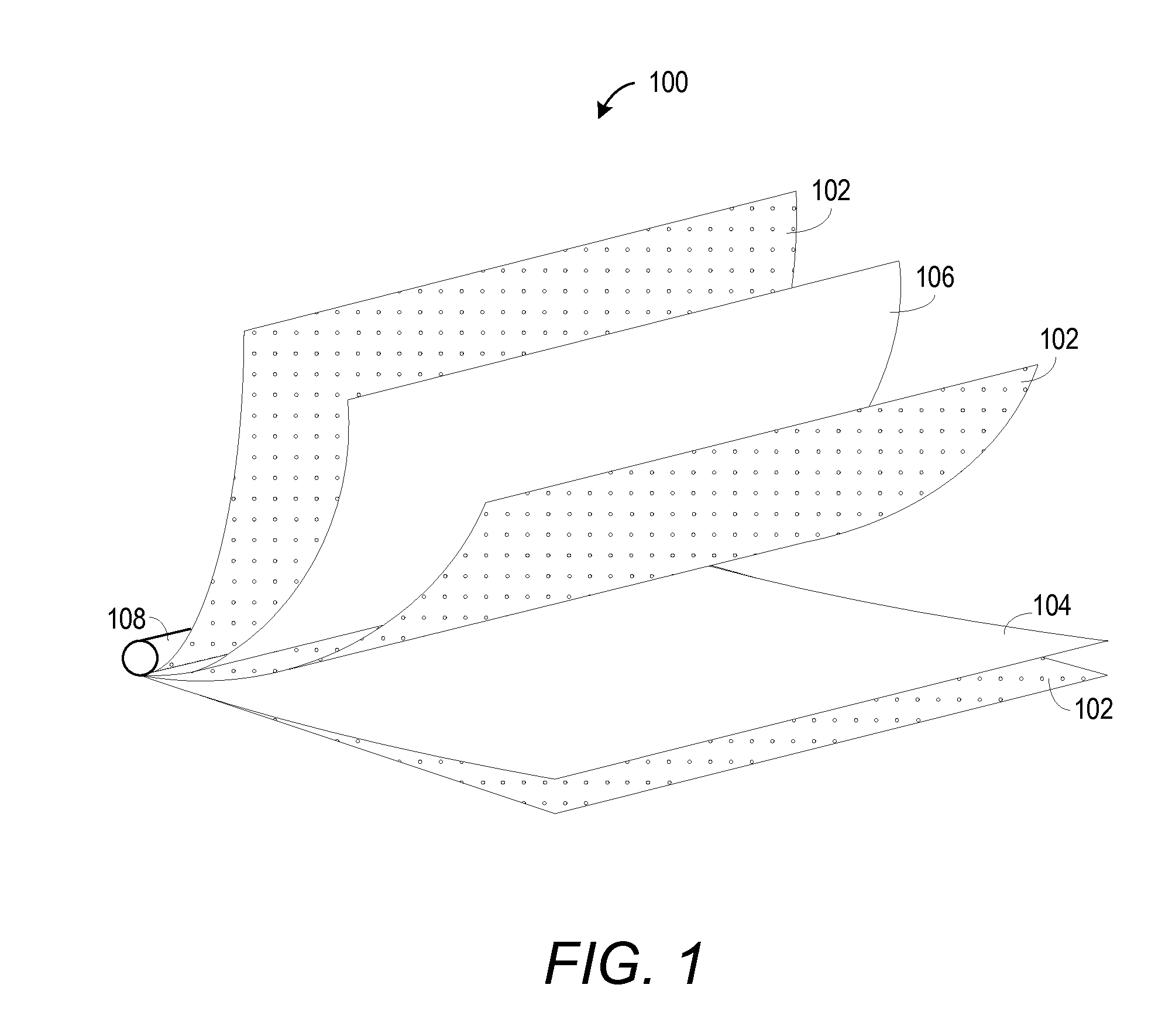
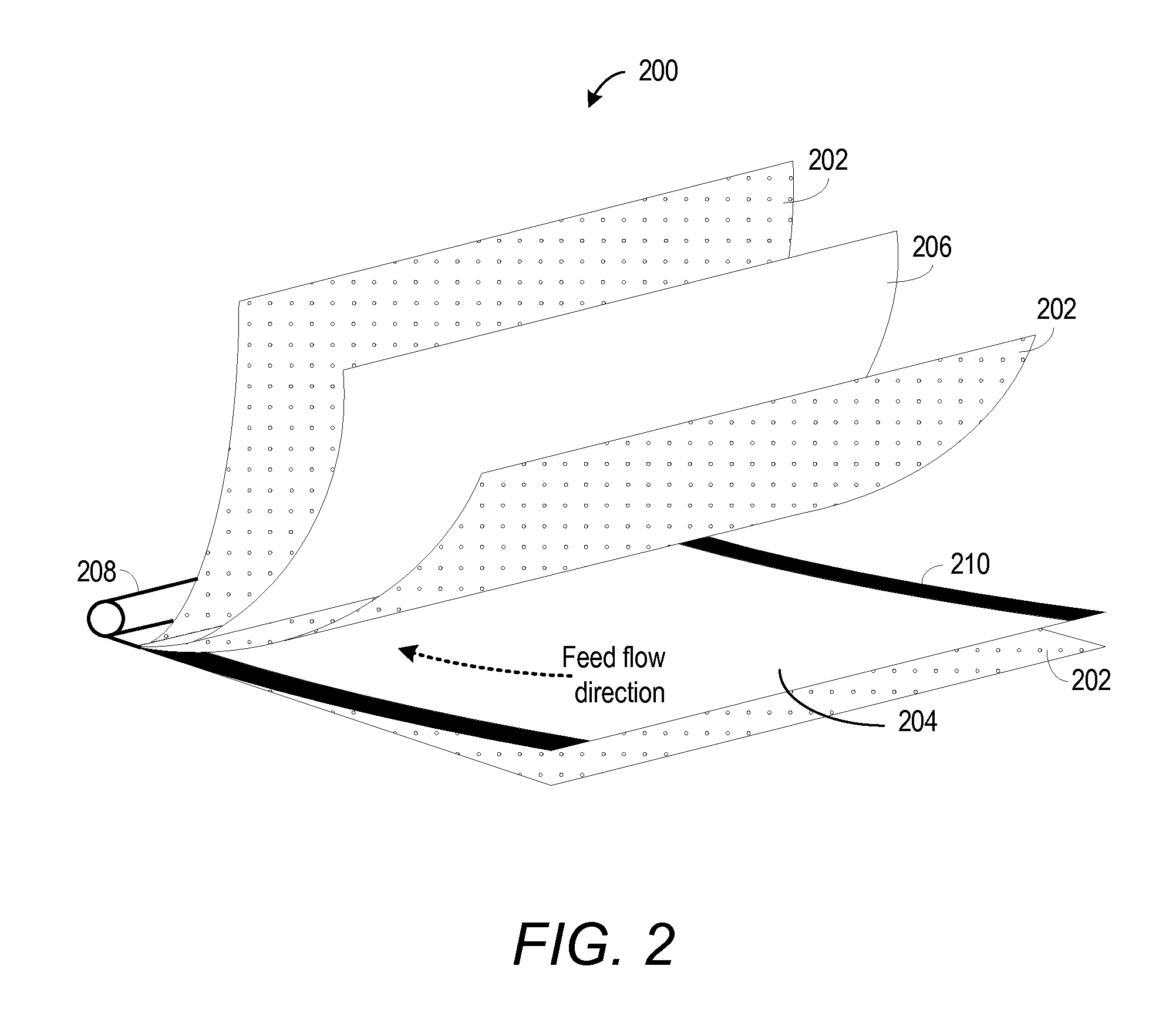
[0020]Embodiments presented herein describe a feed spacer and a separation module employing the feed spacer. Depending on the particular embodiment, the separation module can be used for reverse osmosis, forward osmosis or physical filtration applications. Exemplary embodiments for the applications will become evident through the descriptions provided with the accompanying figures.

[0021]FIG....


PUM

PropertyMeasurementUnit
pressureaaaaaaaaaa
pressureaaaaaaaaaa
flexibleaaaaaaaaaa

Abstract

A separation module utilizing a feed spacer and a method for forming such a separation module are provided. A gasket comprising a flexible waterproof material is disposed on at least part of one or more edges of the feed spacer. A membrane layer is disposed on a first surface of the feed spacer. A permeate carrier is disposed on a surface of the membrane element opposite the feed spacer.

Description

BACKGROUND[0001]Embodiments presented herein relate to a separation module and more particularly to reverse osmosis, forward osmosis, and physical filtration modules. Physical filtration can include micro, ultra and nano filtration processes.[0002]Membrane modules are widely used for separating fluids with dissolved and suspended organic and inorganic solids. Processes used for this purpose can include reverse osmosis, forward osmosis, and physical filtration. In reverse osmosis, a feed solution such as, but not limited to brackish or impure water, sea water, and so forth, is passed through a semi-permeable membrane at a pressure higher than the osmotic pressure of the feed water. A permeate, for example, purified water is obtained on the other side of the semi-permeable membrane.[0003]In forward osmosis, water from a feed solution such as, but not limited to brackish or impure water, seawater, and so forth, is drawn through a semi-permeable membrane due to the osmotic pressure diff...

Claims


Application Information

Patent Timeline
Patent Type & Authority Applications(United States)
IPC IPC(8): B01D61/08B32B38/00B32B37/16
CPCB01D63/103B01D2313/143B01D2313/04B01D65/003B01D2313/041B01D2313/042B01D63/107B01D63/101B01D61/025B01D61/0022
Inventor BEAUCHAMP, PHILIP PAULTHIYAGARAJAN, RAMASAMYKUMAR, ANUBHAVANDERSON, TODD ALAN
Owner GENERAL ELECTRIC CO
Features
  • R&D
  • Intellectual Property
  • Life Sciences
  • Materials
  • Tech Scout
  • Unparalleled Data Quality
  • Higher Quality Content
  • 60% Fewer Hallucinations
Learn More