Self-Optimization of Cell Overlap

a cell overlap and self-optimization technology, applied in the field of self-optimization of cell overlap, can solve the problems of large cell overlap areas, high interference, and only possible signal detection of different base stations

Inactive Publication Date: 2012-05-03
WSOU INVESTMENTS LLC
View PDF3 Cites 21 Cited by
  • Summary
  • Abstract
  • Description
  • Claims
  • Application Information

AI Technical Summary

Benefits of technology

[0037]It is an object of the present invention to provide a self optimization of cell overlap.

Problems solved by technology

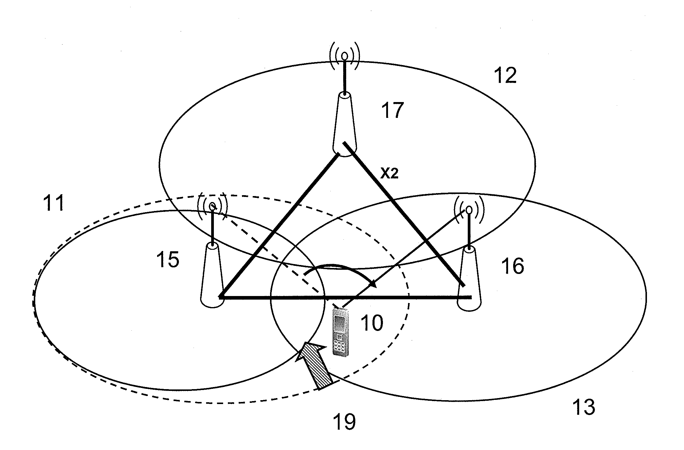
Apparently, the detection of signals from different base stations is only possible in areas covered by more than one base station.
However, inappropriate settings of the transmission power and antenna tilt can lead to large areas of cell overlap.
In these areas many cells are received with similar signal strength so that UEs will suffer from high interference.
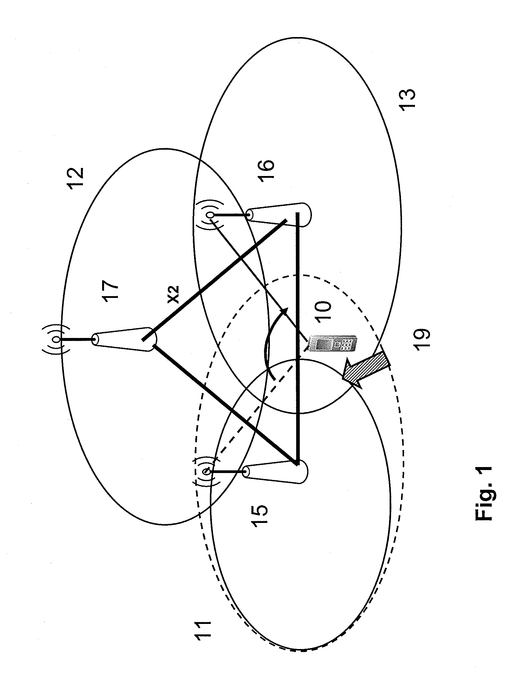
If the cell overlap areas are too large (in FIG. 1, for coverage area / cell 11 indicated by an ellipse in broken line vs. an ellipse in solid line), excessive interference will negatively impact the system capacity and the risk of unnecessary handover between the cells with similar signal strength increases, thus yielding potential impairment on link quality, HO failures, and unnecessary signaling load.
Though, these models have limited accuracy and require high effort.

Method used


Image

  • Self-Optimization of Cell Overlap
  • Self-Optimization of Cell Overlap
  • Self-Optimization of Cell Overlap

Examples


examples

[0138]In the following, implementation examples according to the above described embodiments or forming further certain embodiments of the present invention will be explained.

[0139]In an implementation example the aggregation information is set such that every event is reported immediately. This can minimize effort for storing and processing in the eNB.

[0140]A further implementation example is to set Ncells=2, i.e. the reporting is done based on cell-pairs.

[0141]Still further, if in an implementation example R=3 dB is set, this triggers a reporting as soon as the two best cells (if combined with the preceding example) are received with signal levels (for example the RSRP) not deviating more than 3 dB.

[0142]In a still further implementation example, the eNB forwards the UE measurement reports after removing any bias in the measurements, such as HO offset, HO hysteresis, etc. and adds localization information, for example the timing advance belonging to this measurement report.

[0143]M...


PUM


Abstract

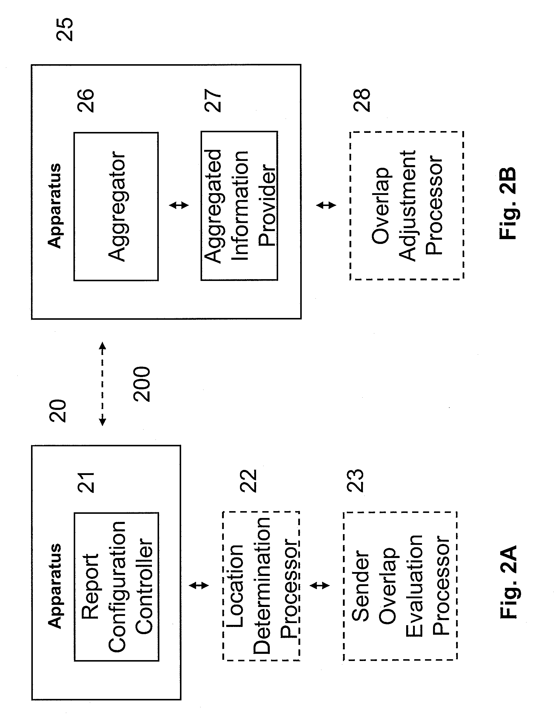
An apparatus includes a report configuration controller configured to command reporting an event defined by receipt of a plurality of signals of different senders, wherein the signals are received at a same location, the signals are received with a strength above an absolute threshold, and a difference of the strengths is within a relative threshold. Another apparatus includes an aggregator configured to aggregate information reflecting an event defined by receipt of a plurality of signals of different senders, wherein the signals are received at a same location, the signals are received with a strength above an absolute threshold, and a difference of the strengths is within a relative threshold; and an aggregated information provider configured to provide the aggregated information.

Description

FIELD OF THE INVENTION[0001]The present invention relates to an apparatus, method, system and computer program product for the self optimization of cell overlap.RELATED BACKGROUND ART[0002]Prior art which is related to this technical field can e.g. be found by the technical specification TS 32.500 current version: 8.0.0) of the 3GPP.[0003]The following meanings for the abbreviations used in this specification apply:[0004]3GPP: 3rd Generation Partnership Project[0005]BS: Base Station[0006]CDF: Cumulative Distribution Function[0007]DM: Domain Manager[0008]EM: Element Manager[0009]eNB: evolved Node B (eNodeB)[0010]FDD: Frequency Division Duplex[0011]GPS: Global Positioning System[0012]HO: Handover[0013]ID: Identity[0014]ISD: Inter Site Distance[0015]Itf-N: Standardized interface between NM and EM or sometimes NM and NE[0016]Itf-?: Interface between EM and NE; “?” is a placeholder, e.g. Itf-R, if NE is a RNC; or Itf-B, if NE is a NodeB[0017]LB: Load Balancing[0018]LTE: Long Term Evoluti...

Claims


Application Information

Patent Timeline
Patent Type & Authority Applications(United States)
IPC IPC(8): H04W24/00
CPCH04W24/02H04W16/00
Inventor VIERING, INGODOETTLING, MARTIN
Owner WSOU INVESTMENTS LLC
Why Eureka
Try Eureka