Flexible artificial retina devices

a technology of artificial retina and integrated circuit, which is applied in the field of micro devices, can solve the problems of increasing the number of electrical interconnections between the micro electrode chip and the driving circuit chip, severely limited field of view provided by such devices, and achieves the effect of high electrical excitation resolution

Active Publication Date: 2012-05-03
IRIDIUM MEDICAL TECH
View PDF9 Cites 95 Cited by
  • Summary
  • Abstract
  • Description
  • Claims
  • Application Information

AI Technical Summary

Benefits of technology

The patent describes a flexible device that can provide high-resolution electrical stimulation to the retina, allowing for precise targeting of individual cells. The device can be implanted using either an epi-retinal or sub-retinal approach. The technical effect is improved precision and accuracy in retina prosthesis.

Problems solved by technology

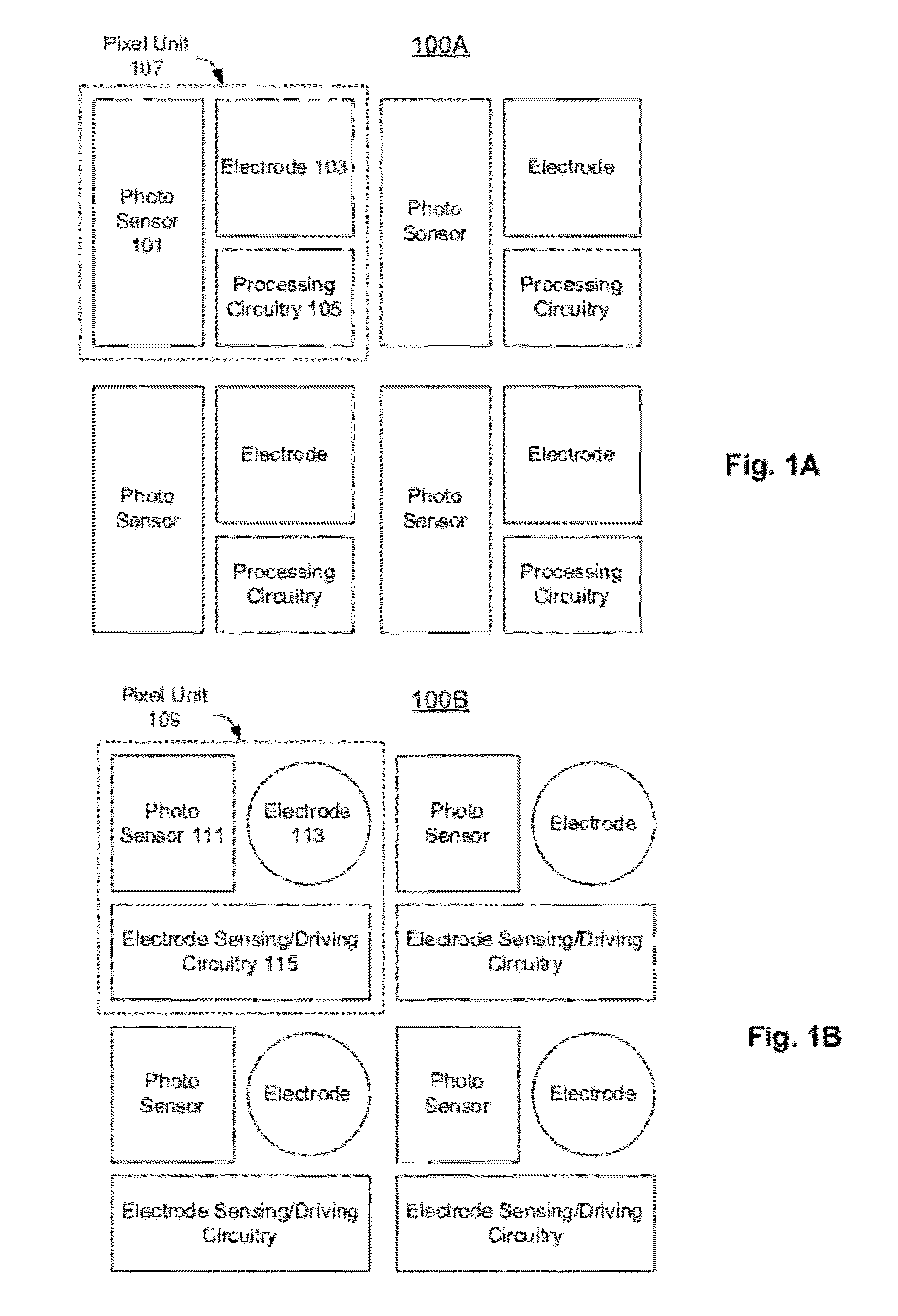
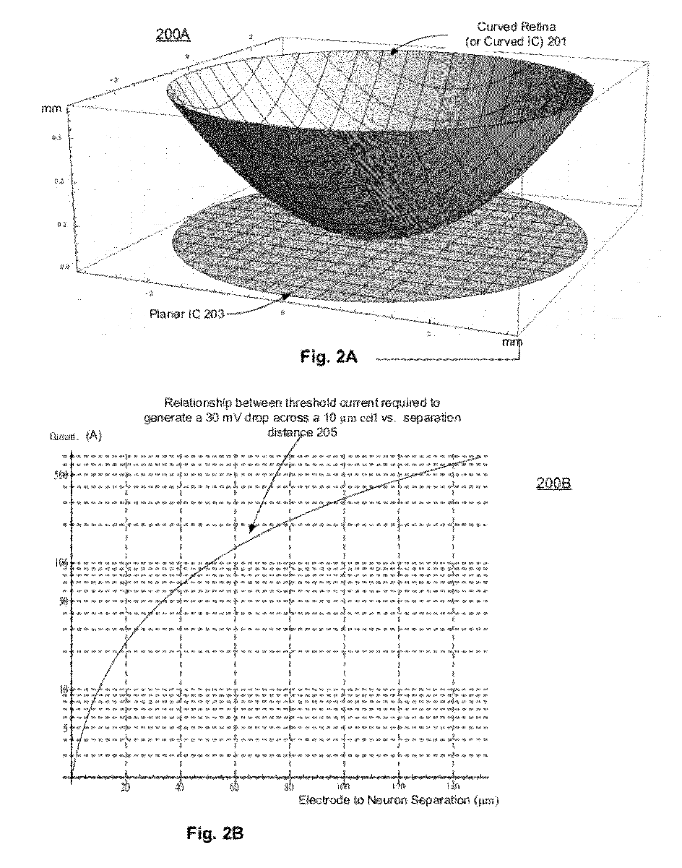
The technical problem addressed in this patent is the limitations of traditional retina prosthesis devices in providing high levels of image resolution, field of views, and other visual characteristics close to a real retina to help patients recover from impaired vision capabilities. These devices are also limited by the size limitation on the wiring implant and the mismatch of micro electrode shapes to non-planar shapes of retina tissues.

Method used


Image

  • Flexible artificial retina devices
  • Flexible artificial retina devices
  • Flexible artificial retina devices

Examples


Embodiment Construction

[0032]Flexible artificial retina devices are described herein. In the following description, numerous specific details are set forth to provide thorough explanation of embodiments of the present invention. It will be apparent, however, to one skilled in the art, that embodiments of the present invention may be practiced without these specific details. In other instances, well-known components, structures, and techniques have not been shown in detail in order not to obscure the understanding of this description.

[0033]Reference in the specification to “one embodiment” or “an embodiment” means that a particular feature, structure, or characteristic described in connection with the embodiment can be included in at least one embodiment of the invention. The appearances of the phrase “in one embodiment” in various places in the specification do not necessarily all refer to the same embodiment.

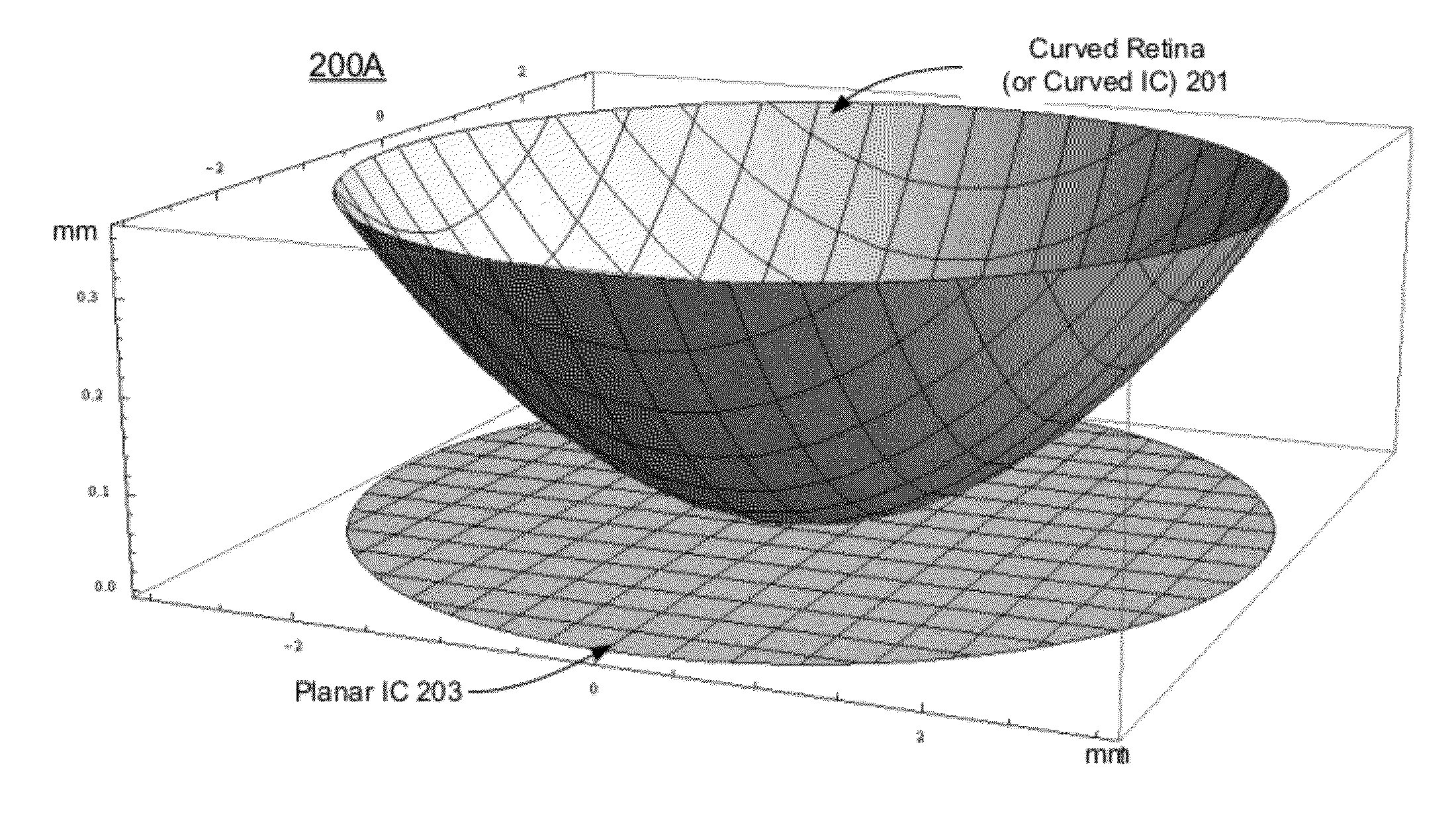
[0034]A flexible IC (integrated circuit) device can integrate an array of “pixels” in a sing chip...


PUM


Abstract

An implant apparatus comprising a plurality of photo sensors, a plurality of micro electrodes and circuitry coupled to the photo sensors and the micro electrodes are described. The photo sensors may receive incoming light. The circuit may drive the micro electrodes to stimulate neuron cells for enabling perception of a vision of the light captured by the photo sensors. The apparatus may be implemented in a flexible material to conform to a shape of a human eyeball to allow the micro electrodes aligned with the neuron cells for the stimulation.

Description


Claims


Application Information

Patent Timeline
Owner IRIDIUM MEDICAL TECH
Why Eureka
Try Eureka