
Milk tube dome with flow controller

a technology of flow controller and milk tube, which is applied in the field of milker unit liners with internal flow diverters, can solve the problems of multiple nozzles, increased manufacturing costs, and clogging of tubes and chambers, and achieve uniform teat dip coverage, uniform teat dip delivery, and reduced amount of teat dip applied

Active Publication Date: 2012-05-10
GEA FARM TECH INC
View PDF8 Cites 27 Cited by
  • Summary
  • Abstract
  • Description
  • Claims
  • Application Information

AI Technical Summary

Benefits of technology

[0012]The present invention overcomes problems associated with teat dip delivery through small or multiple orifices and nozzles formed in milking liner domes. The present invention provides more uniform delivery of teat dip to an upper portion of a teat and / or the lower portion of a cow udder while reducing the amount of teat dip applied, as well as the number of nozzles and orifices that might otherwise be required to obtain substantially uniform teat dip coverage. Further, the liner mouthpiece wipes the teat dip down the teat when the milker unit drops from the cow at the end of milking.
[0013]The present invention is a milker unit liner dome that includes internal flow diverters that simplify teat dip distribution and make liner cleaning easier and more thorough. Also, because liners are relatively inexpensive and are replaced regularly, the flow diverter geometry of the liner can be updated without undue expense.
[0014]The present invention simplifies distribution of teat dip with a liner dome design that requires no assembly and is relatively inexpensive to manufacture. Further, dips of various viscosities can be used with reduced clogging.
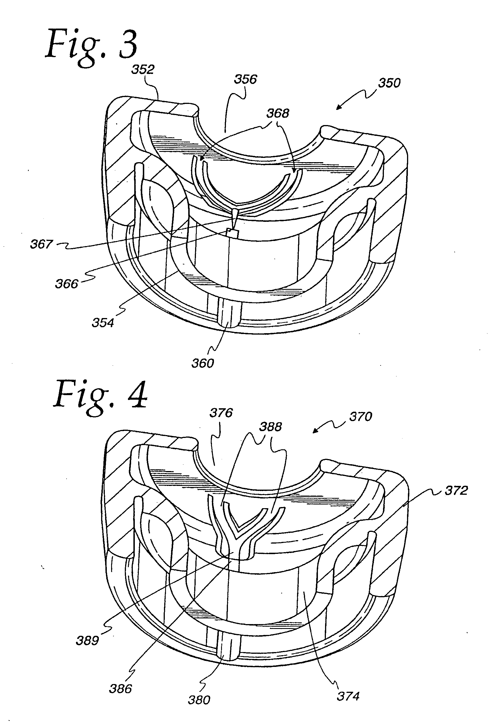
[0015]A milker unit liner in accordance with the present invention includes a dome having an opening through which a cow's teat extends during milking. When a teat is inserted, a dome chamber is essentially divided into an annular space. A liner dome in accordance with the present invention has joined to its inner surface a flow diverter such as a ramp, channel, vane, ridge, or other shape to direct flow of teat dip and / or cleaning fluid from an inlet to all portions of the teat including the side that is opposite the teat dip inlet. A flow diverter in accordance with the present invention improves the flow characteristics of dip through the dome as compared to a standard dome chamber.
[0016]The present invention may include an improved inlet or nozzle in the form of a slit in the liner and acts essentially as a one-way valve to prevent milk, cleaning fluid, or debris from flowing or being forced into the teat dip delivery hole. The slit can be molded into the dome or cut after the molding process used to manufacture the dome. The inlet may also be a simple hole with the supply tube blocked at times to prevent vacuum leakage or backflow of fluids. This hole or port can then be cleaned each time the dipping process takes place.

Problems solved by technology

Given the confined nature of the liners within teat cup shells, tubes and chambers must be relatively small, and can be subject to clogging.
Multiple nozzles also present increased manufacturing costs.
Teat dips cannot be mixed with milk.

Method used


Image

  • Milk tube dome with flow controller
  • Milk tube dome with flow controller
  • Milk tube dome with flow controller

Examples


Embodiment Construction

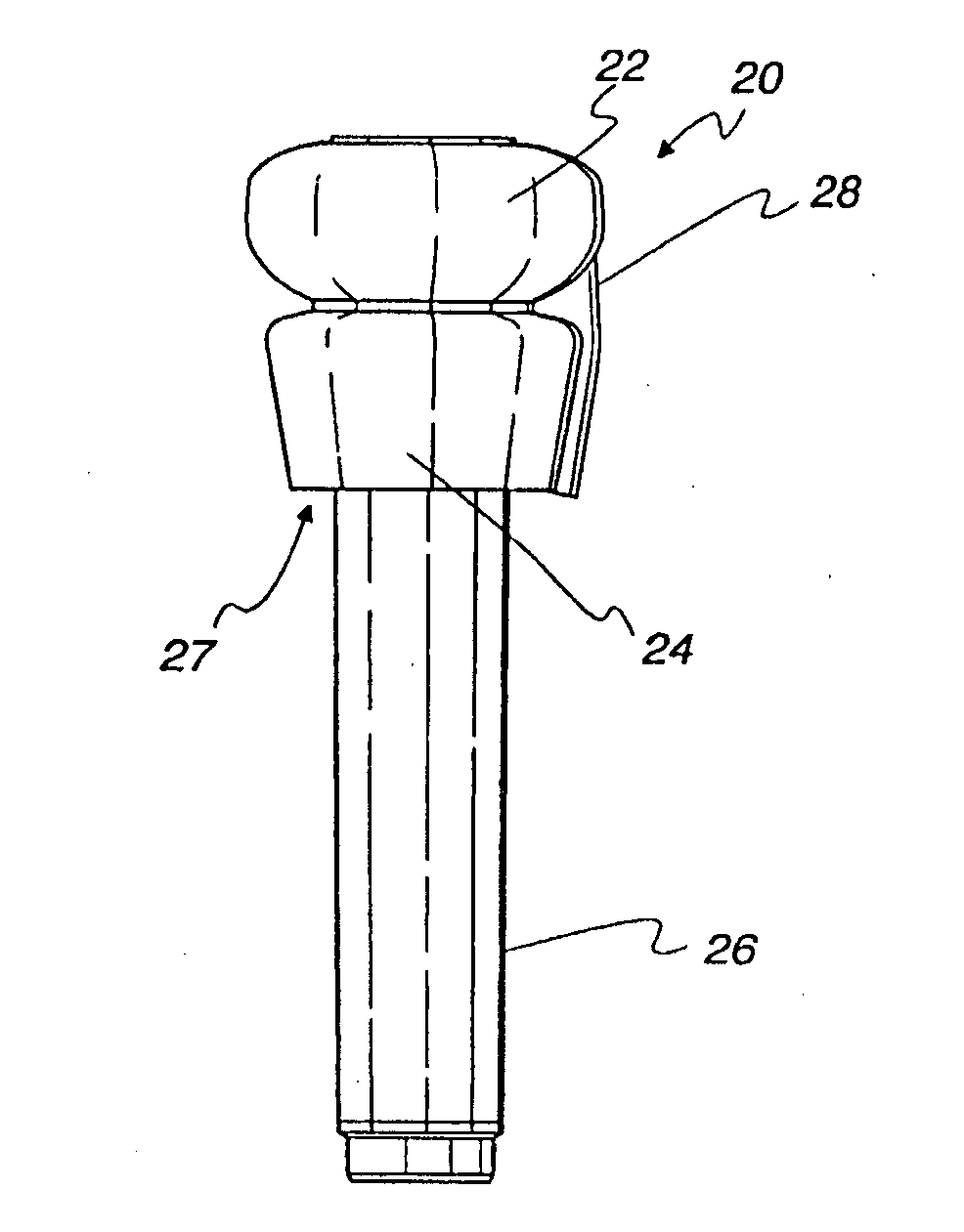
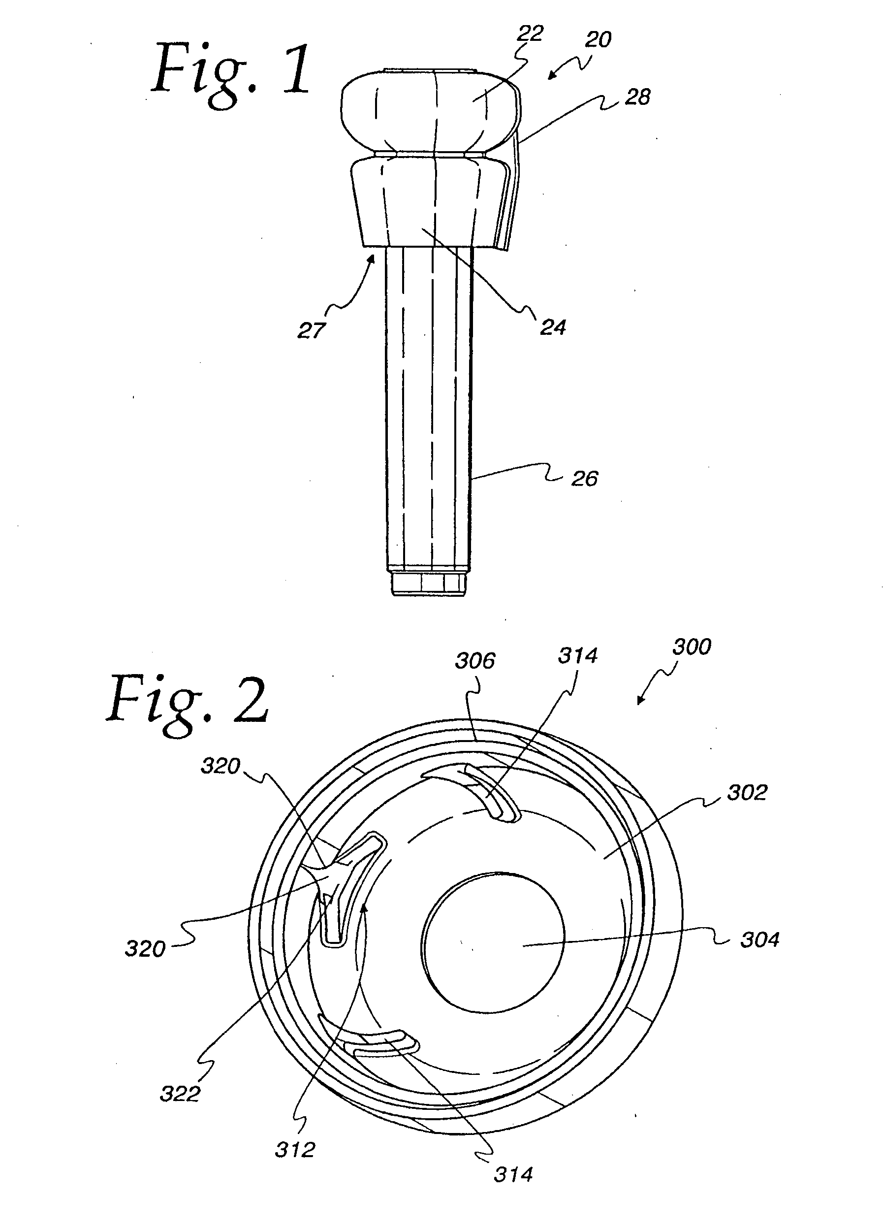
[0029]In FIG. 1, there is depicted a milker unit liner 20 in accordance with the present invention. The liner 20 includes a dome 22, a skirt 24, a barrel 26, and a delivery channel 28. The skirt 24 extends downward from the dome 22 and is spaced away from the barrel 26 to define a recess 27.

[0030]The liner 20 is sized and shaped to fit into a conventional outer shell or “teat cup” (not illustrated) so that the top of the teat cup fits in the recess 27 between the skirt 24 and the barrel 26. This relationship secures the liner 20 to the teat cup and forms a seal for the vacuum. The liner barrel 26 may have any cross-sectional shape including round and square. Alternatively, a liner can comprise a separate dome and barrel that are connected to each other directly or indirectly using a teat cup or the other suitable device. The present invention is directed to a dome 22 having an inner surface to which flow diverters are joined regardless of the type, size, or shape of barrel. The line...


PUM


Abstract

A milker unit liner dome having an inner surface and flow diverters joined to the inner surface to redirect teat dip from an inlet to provide more uniform coverage of dip on a teat. The liner dome can also include more than one flow diverter for redirecting teat dip flow.

Description

[0001]This application is a continuation of U.S. patent application Ser. No. 12 / 215,706, filed Jun. 27, 2008, which is incorporated herein by reference in its entirety.FIELD AND BACKGROUND OF THE INVENTION[0002]This invention relates generally to dairy milker unit liners and more particularly to milker unit teat cup liners with internal flow diverters for distributing teat dip before a milker unit is detached from an animal being milked.[0003]Milking machines are attached to dairy animals to withdraw and collect milk. The part of the milking machine that interfaces with the dairy animal includes an outer shell, called a teat cup, and an interior liner. A dairy animal's teat is inserted into a top opening in the teat cup and liner for milking. With vacuum hoses connected to these components, a pulsation is created that withdraws milk from the dairy animal's teat.[0004]Liners are shaped and sized to maximize animal comfort, and to be efficient and responsive to the vacuum that causes ...

Claims


Application Information

Patent Timeline
Patent Type & Authority Applications(United States)
IPC IPC(8): A01J5/06
CPCA01J7/04A01J5/06
Inventor TORGERSON, KEVIN L.SELLNER, DUANE F.
Owner GEA FARM TECH INC
Learn More