Arm for spectacles and associated spectacles

a technology for spectacles and arms, applied in the field of arms for spectacles and spectacles, can solve the problems of limiting the possibility of positioning decorative elements around only these straight portions of the frame, complex and expensive design, and risking losing decorative elements by having them detach, so as to achieve simple and inexpensive design, easy manipulation for users, and the effect of not risking loss

Inactive Publication Date: 2012-05-10
KILLINE OPTICAL
View PDF3 Cites 17 Cited by
  • Summary
  • Abstract
  • Description
  • Claims
  • Application Information

AI Technical Summary

Benefits of technology

[0006]The present invention in particular aims to resolve all or part of the drawbacks mentioned above, by proposing a spectacle arm provided with at least one decorative element having a simple and inexpensive design, easy for the user to manipulate to modify the appearance of the spectacle arms, and without risk of loss.

Problems solved by technology

To modify the appearance of the spectacles, and more particularly the arms of the spectacles, it is known, in particular from document US 2009 / 0096982 A1, to position removable decorative elements on the arms of the spectacles, with the drawback of risking losing the decorative elements by having them detach from the arms of the spectacles.
Such decorative arms have the main drawback of having a complex and expensive design, as they require means for locking the pivoting decorative element in position.
Furthermore, such a decorative element can only be mounted around a straight portion of the frame so as to allow said rigid decorative element to rotate, thereby limiting the possibilities for positioning decorative element around only these straight portions of the frame.

Method used


Image

  • Arm for spectacles and associated spectacles
  • Arm for spectacles and associated spectacles
  • Arm for spectacles and associated spectacles

Examples


first embodiment

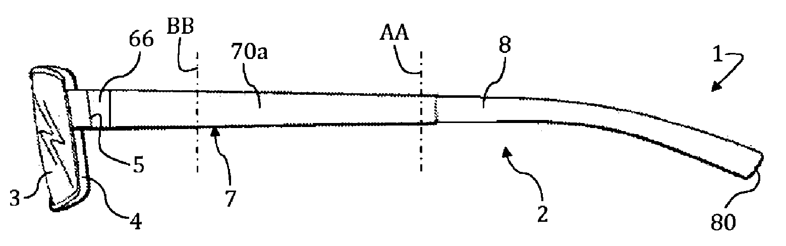
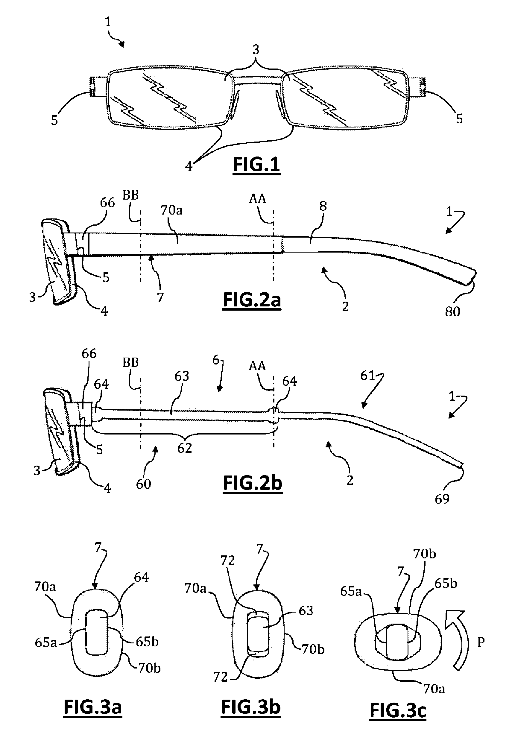
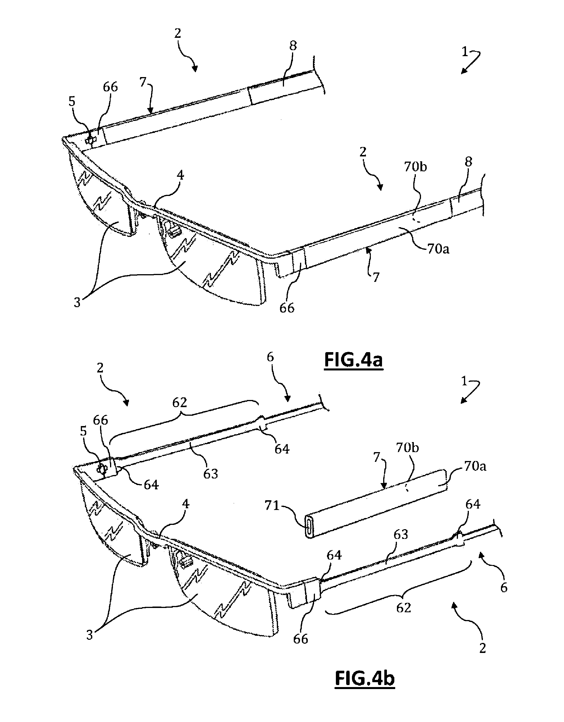
[0084]The description below relates to the spectacles 1 and arms 2, done in reference to FIGS. 1 to 4.

[0085]The sleeve 7 is mounted around a segment 62 of the frame 6, said segment 62 having a central portion 63 and two end portions 64 and defining two opposite support surfaces, front 65a (on the side opposite the spectacles wearer) and rear 65b (on the side of the spectacles wearer), respectively.

[0086]This segment 62 is situated in the front part 60 of the frame 6. The central portion 63 has a constant section and oblong shape. Each end portion 64 has widened section relative to the central portions 63 and also has an oblong shape, i.e. the end portions 64 are wider than the central portion 63.

[0087]The internal housing 70 of the sleeve 7 has a substantially constant section, with an oblong shape, so as to at least partially hug the segment 62 of the frame 6 over the entire length of the segment 62.

[0088]As visible in FIG. 3a, the sleeve 7 is mounted substantially without play aro...

second embodiment

[0092]The description below relates to the spectacles 1 and arms 2, done in reference to FIGS. 5 to 6.

[0093]The sleeve 7 is mounted around a central segment 67 of the frame 6. The central segment 67 is situated in the front part 60 of the frame 6, and has a constant section and oblong shape over its entire length. In that case, the central portion and the end portions of said central segment 67 are identical in terms of shape and dimensions, compared to the segment 62 described above for the first embodiment.

[0094]The central segment 67 is framed by a rear segment 68 of the frame 6, around which the tip 8 is mounted, and the front edge 66 of the frame 6 on which the hinge 5 is partially fixed, where said front edge 66 has a dimension larger than that of the central segment 67.

[0095]The internal housing 71 of the sleeve 7 has a substantially constant section and oblong shape.

[0096]As visible in FIGS. 6a to 6c, the sleeve 7 is mounted substantially without play around the central segm...

third embodiment

[0098]The description below relates to the spectacles 1 and arms 2, done in reference to FIGS. 7.

[0099]The spectacles 1 have several sleeves 7 mounted around the frame 6. In the case at hand, these sleeves 7 are successively mounted one behind the other along the frame 6. It is of course possible to consider providing intermediate pieces mounted around the frame 6 and inserted between the sleeves 7 and / or to provide intermediate segments of the frame 6 between the sleeves 7.

[0100]The description below relates to fourth, fifth, sixth and seventh embodiments of the spectacles 1 and arms 2, done in reference to FIGS. 8 to 11, respectively.

[0101]In these embodiments, the sleeve 7 comprises at least one first part 72, 74, 76 completely made from an elastically deformable material, and at least one rigid second part 73, 75, 77 secured to the first part 72, 74, 76 and defining at least one decorative surface 70c, 70d.


PUM


Abstract

The invention relates to an arm (2) for spectacles (1) including a frame (6), characterized in that it comprises at least one decorative sleeve (7) at least partially made of an elastically deformable material, provided with at least one decorative surface (70a, 70b) and mounted around the frame (6) of the arm (2), said sleeve (7) being designed to turn and/or twist around the frame (6) by means of elastic deformation in order to modify the appearance of said arm (2). The invention also relates to the spectacles (1) provided with such an arm (2). The present invention can be used in the field of spectacles

Description

TECHNICAL FIELD[0001]The present invention relates to an arm for spectacles and spectacles equipped with such an arm.BRIEF DISCUSSION OF RELATED ART[0002]In a known manner, spectacles include a face, sometimes called optical façade, provided with lenses, for example such as optical and / or solar and / or protective and / or safety lenses, said face possibly being supported by a spectacle frame, and two spectacle arms, called side arms, connected to the face or frame of the spectacles via a pin and an associated hinge.[0003]It is common practice for a spectacle arm to include a rigid frame in particular made from steel, a composite material, or a rigid plastic, which is essentially made up of two parts, i.e. a generally straight front portion intended to be connected to the face or frame of the spectacles, and a generally curved back portion intended to fit around the back of the ear and possibly to bear on the ear.[0004]To modify the appearance of the spectacles, and more particularly th...

Claims


Application Information

Patent Timeline
Patent Type & Authority Applications(United States)
IPC IPC(8): G02C11/02
CPCG02C11/02G02C5/18
Inventor JACQUIER, HERVE FRANCOIS SERGEVERMET, CHRISTIAN FRANCOIS YVES
Owner KILLINE OPTICAL
Why Eureka
Try Eureka