Fixing Device, Image Forming Apparatus Incorporating Same, And Method For Fixing Toner Image On Recording Medium

a technology of toner image and fixing device, which is applied in the direction of electrographic process apparatus, instruments, optics, etc., can solve the problems of overheating of the fixing roller, wasting power, and controlling the heating method

Active Publication Date: 2012-05-10
RICOH KK
View PDF4 Cites 62 Cited by
  • Summary
  • Abstract
  • Description
  • Claims
  • Application Information

AI Technical Summary

Benefits of technology

[0017]FIG. 6 is a flowchart showing processes of a control method according to a first embodiment performed by the controller shown in FIG. 4; and
[0018]FIG. 7 is a flowchart showing processes of a control method according to a second embodiment performed by the controller shown in FIG. 4.

Problems solved by technology

However, if the heater heats the fixing roller even after the recording medium is discharged from the fixing nip, the fixing roller may be overheated.
However, this control method for controlling the heater has a drawback when used in conjunction with a configuration of the fixing device in which the heater is disposed a given distance upstream from the fixing nip in the direction of rotation of the fixing roller.
For example, even if the heater is turned off after the trailing edge of the recording medium enters the fixing nip, the heater has already heated an upstream section on the surface of the fixing roller upstream from the fixing nip in the direction of rotation of the fixing roller that will not contact the recording medium and therefore is not used for fixing the toner image on the recording medium, thus wasting power.

Method used


Image

  • Fixing Device, Image Forming Apparatus Incorporating Same, And Method For Fixing Toner Image On Recording Medium
  • Fixing Device, Image Forming Apparatus Incorporating Same, And Method For Fixing Toner Image On Recording Medium
  • Fixing Device, Image Forming Apparatus Incorporating Same, And Method For Fixing Toner Image On Recording Medium

Examples


first embodiment

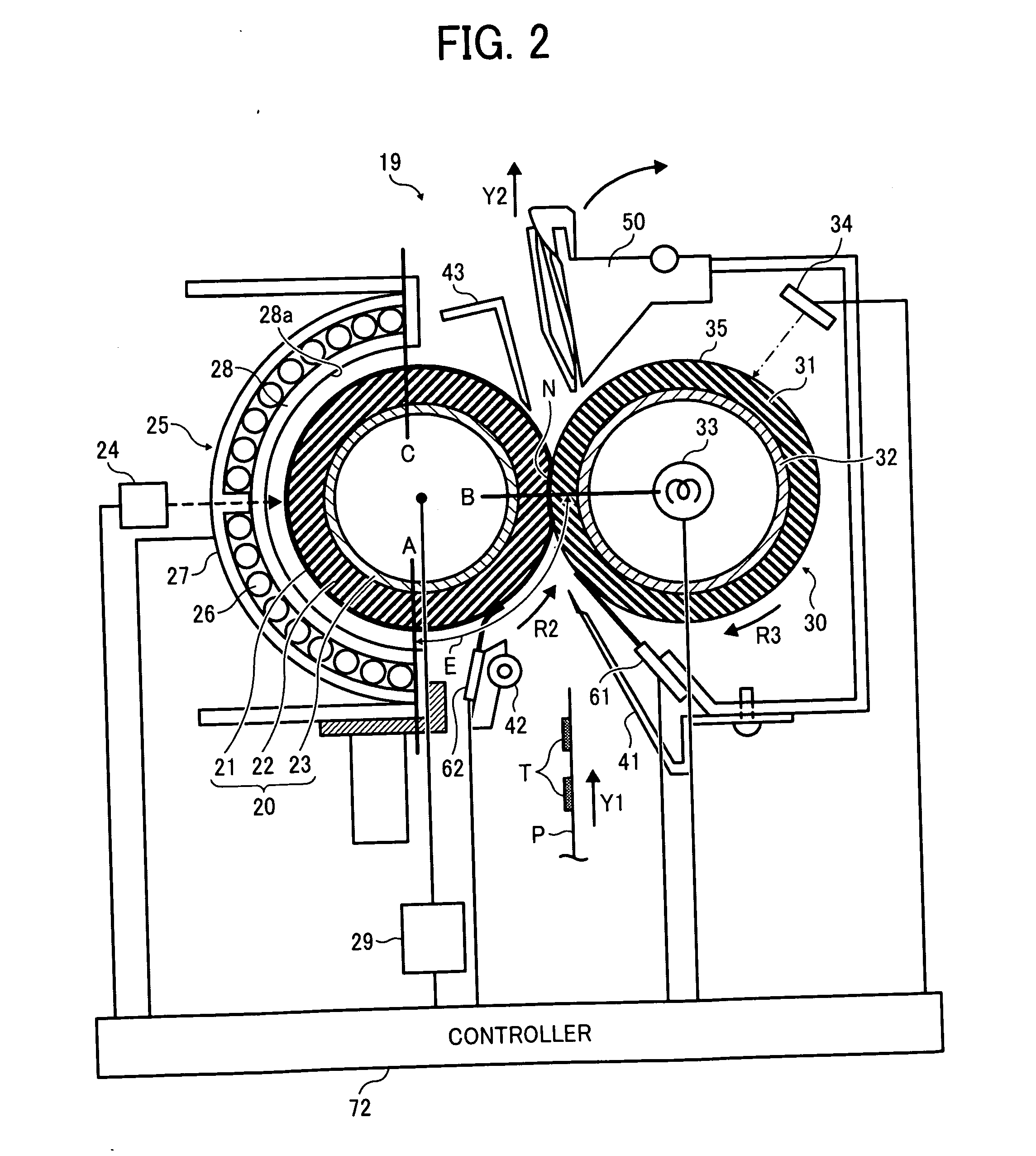
[0081]Referring to FIGS. 2 to 6, the following describes a control method for controlling the temperature of the fixing roller 20 which may be performed when the last recording medium P is conveyed through the fixing device 19 in a particular print job.

[0082]FIG. 4 is a block diagram of the controller 72 and the induction heater 25. As illustrated in FIG. 4, the controller 72 includes a heater driver 69 operatively connected to the induction heater 25 to turn on the induction heater 25; a heater driver controller 71 operatively connected to the heater driver 69 to control the heater driver 69; and a timing calculator 70 operatively connected to the heater driver controller 71.

[0083]As recording media P of a particular print job pass through the fixing nip N formed between the fixing roller 20 and the pressing roller 30, the recording media P draw heat from the fixing roller 20. Accordingly, when the last recording medium P of the print job is discharged from the fixing nip N, the f...

second embodiment

[0104]Referring to FIGS. 2 to 5 and 7, the following describes processes of the control method described above.

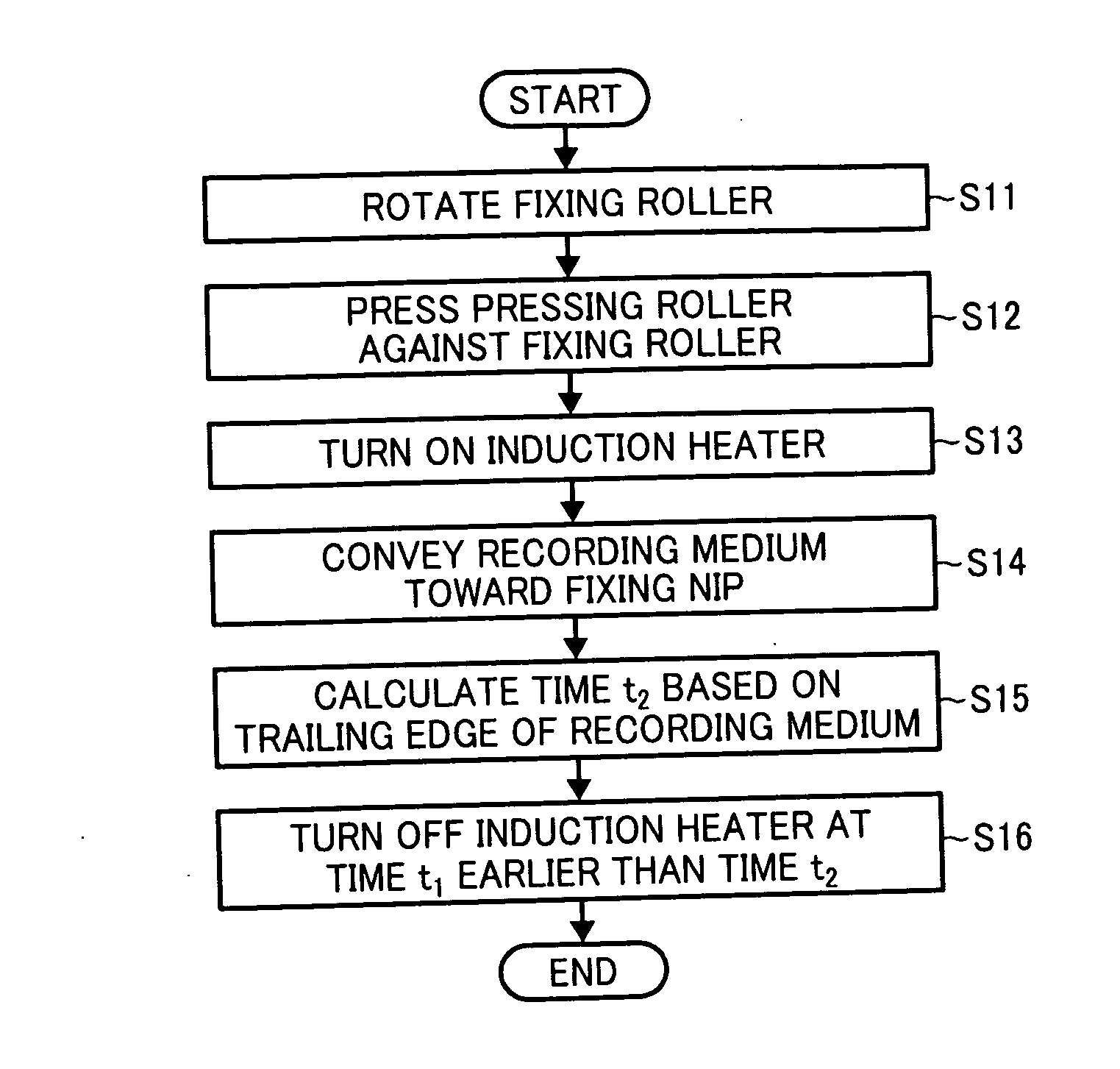
[0105]FIG. 7 is a flowchart showing the processes of the control method according to the second embodiment.

[0106]In step S21, the driver 29 rotates the fixing roller 20 in the rotation direction R2. In step S22, the pressing roller 30 is pressed against the fixing roller 20 to form the fixing nip N therebetween. Accordingly, the rotating fixing roller 20 rotates the pressing roller 30 in the rotation direction R3 by friction therebetween. In step S23, the heater driver 69 turns on the induction heater 25 to heat the fixing roller 20. In step S24, the recording medium P is conveyed toward the fixing nip N. In step S25, the timing calculator 70 calculates the time t2 at which the trailing end of the toner image T on the recording medium P in the conveyance direction of the recording medium P reaches the position B of the fixing nip N. In step S26, the heater driver controlle...


PUM


Abstract

A fixing device includes a pressing rotary body pressed against a fixing rotary body to form a fixing nip therebetween through which a recording medium bearing a toner image is conveyed; a heater to heat the fixing rotary body, disposed opposite a circumferential surface of the fixing rotary body and upstream from the fixing nip a predetermined circumferential distance along the circumferential surface of the fixing rotary body in a direction of rotation of the fixing rotary body; a heater driver to turn on and off the heater; a timing calculator to calculate a reference time at which a trailing end portion of the recording medium in a conveyance direction of the recording medium reaches the fixing nip; and a heater driver controller to cause the heater driver to turn off the heater at a turn-off time earlier than the reference time.

Description

CROSS-REFERENCE TO RELATED APPLICATIONS[0001]This patent application is based on and claims priority pursuant to 35 U.S.C. §119 to Japanese Patent Application Nos. 2010-252055, filed on Nov. 10, 2010, and 2010-271607, filed on Dec. 6, 2010, in the Japan Patent Office, the entire disclosure of each of which is hereby incorporated by reference herein.FIELD OF THE INVENTION[0002]Example embodiments generally relate to a fixing device, an image forming apparatus, and a method for fixing a toner image on a recording medium, and more particularly, to a fixing device for fixing a toner image on a recording medium, an image forming apparatus including the fixing device, and a method used by the fixing device.BACKGROUND OF THE INVENTION[0003]Related-art image forming apparatuses, such as copiers, facsimile machines, printers, or multifunction printers, having at least one of copying, printing, scanning, and facsimile functions, typically form an image on a recording medium according to image...

Claims


Application Information

Patent Timeline
Patent Type & Authority Applications(United States)
IPC IPC(8): G03G15/20
CPCG03G15/2046
Inventor SAITO, KAZUYAOGAWA, TADASHIUCHITANI, TAKESHIUENO, SATOSHIKAWATA, TEPPEIHASE, TAKAMASAYUASA, SHUUTAROHYAMAJI, KENSUKE
Owner RICOH KK
Why Eureka
Try Eureka