Pneumatic tire

a technology of pneumatic tires and treads, which is applied in the direction of non-skid devices, vehicle components, transportation and packaging, etc., can solve the problems of uneven wear on the outer side of the vehicle, uneven wear is prone to be generated, and the tread rigidity at the shoulder portion is deteriorated, so as to enhance uneven wear resistance, smooth guide water, and reduce the effect of deterioration

a technology of pneumatic tires and treads, which is applied in the direction of non-skid devices, vehicle components, transportation and packaging, etc., can solve the problems of uneven wear on the outer side of the vehicle, uneven wear is prone to be generated, and the tread rigidity at the shoulder portion is deteriorated, so as to enhance uneven wear resistance, smooth guide water, and reduce the effect of deterioration

US20120118455A1Active Publication Date: 2012-05-17SUMITOMO RUBBER IND LTD

Image

  • Pneumatic tire
  • Pneumatic tire
  • Pneumatic tire

Examples


example

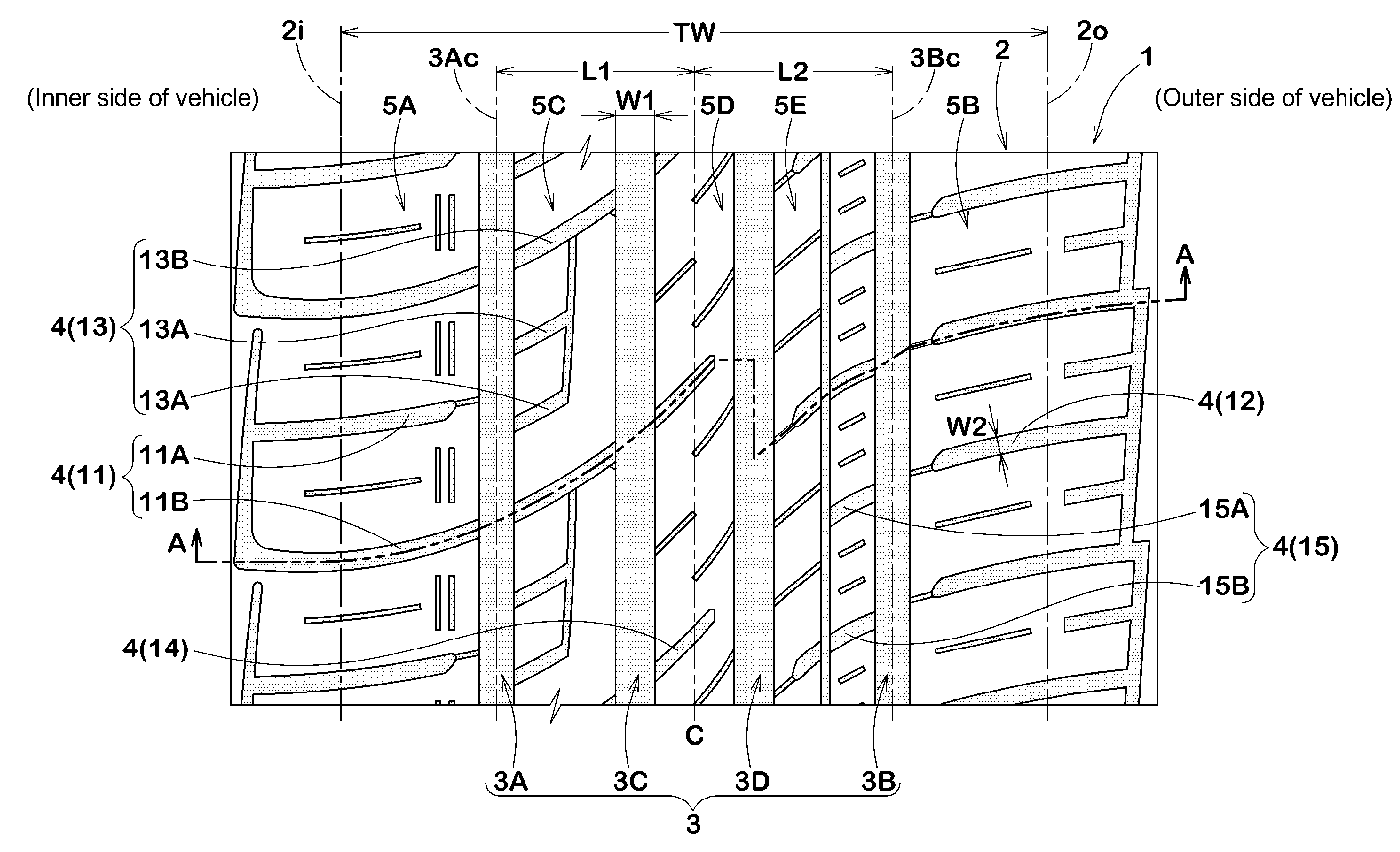
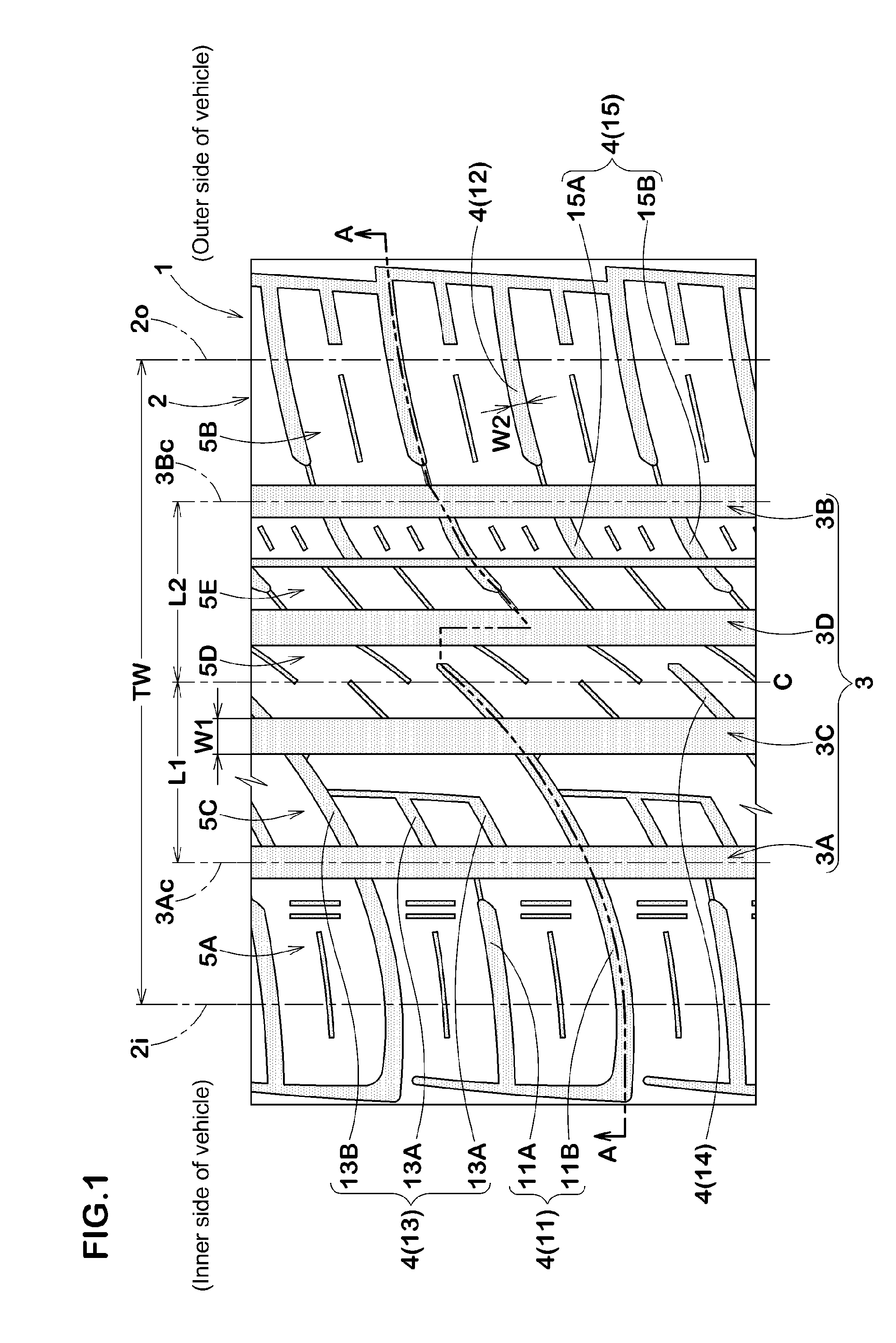
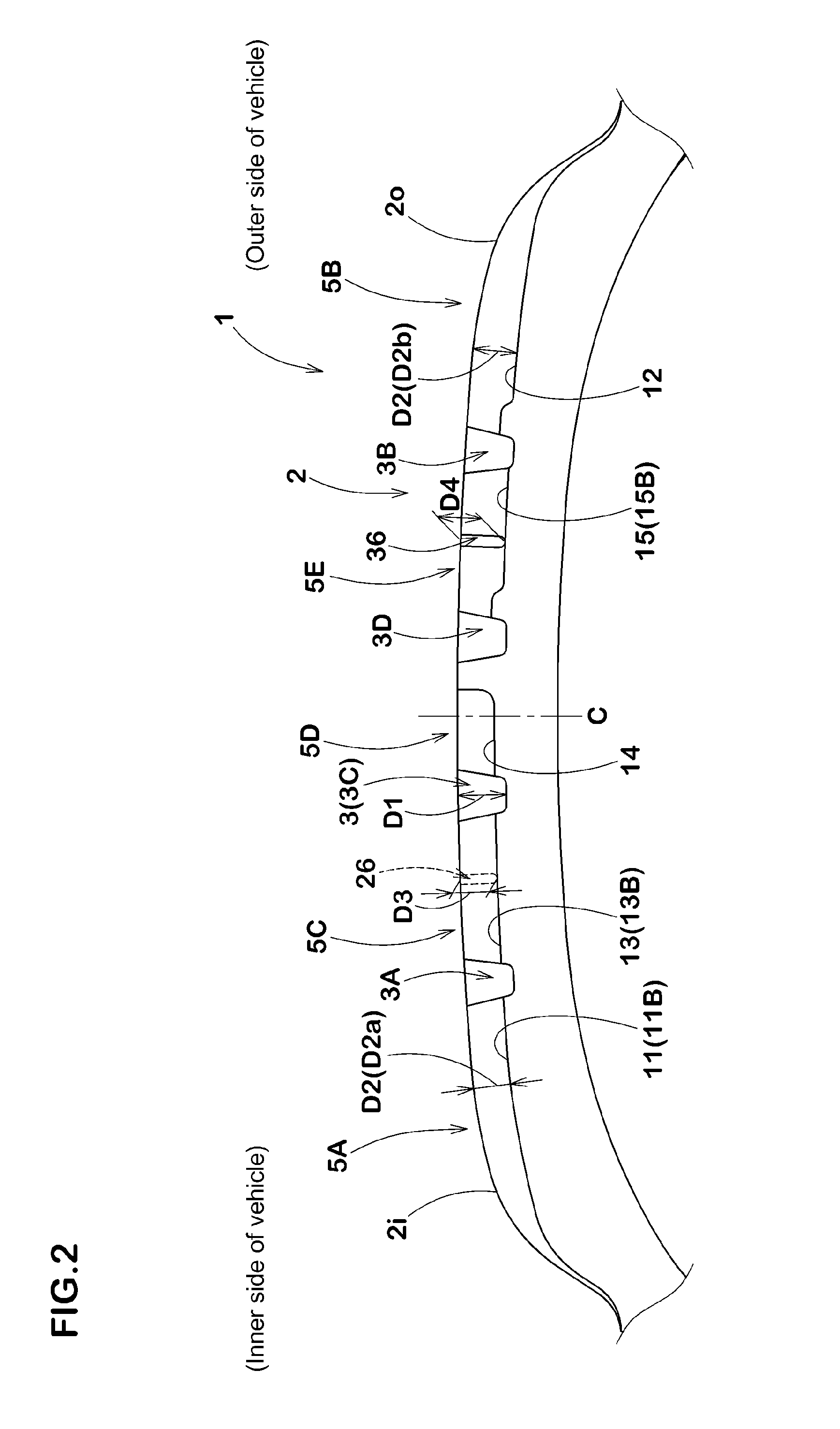
[0077]Tires having the basic structure shown in FIG. 1, and having the circumferential grooves and the lateral grooves shown in Table 1 were produced, and performance levels of the tires were evaluated. For comparison, tires in which the inner shoulder lateral grooves and the outer shoulder lateral grooves shown in FIG. 5 were laterally inverted are also produced, and performance levels of the tires were evaluated likewise. Common specifications are as follows:

tire size: 225 / 55R17 97V

rim size: 17×7.0 JJ

tread width TW: 194 mm

circumferential groove:

[0078]groove width W1: 8.5 mm

[0079]groove depth D1: 9.0 mm

[0080]ratio (W1 / TW): 4.4%

[0081]ratio (D1 / TW): 4.6%

[0082]inner shoulder circumferential groove:[0083]distance L1 from tire equator of groove center line: 50.5 mm[0084]ratio (L1 / TW): 26.0%

[0085]outer shoulder circumferential groove:[0086]distance L2 from tire equator of groove center line: 50.4 mm[0087]ratio (L2 / TW): 26.0%

lateral groove:

[0088]groove width W2: 4.9 mm

[0089]groove depth D...


PUM


Abstract

To make it possible to enhance uneven wear resistance while maintaining drainage performance, a pneumatic tire includes a left-right asymmetric tread pattern having a designated mounting orientation with respect to a vehicle. Vertical grooves include an inner shoulder circumferential groove disposed on an innermost side of the vehicle, and an outer shoulder circumferential groove disposed on an outermost side of the vehicle. Lateral grooves include inner shoulder lateral grooves and outer shoulder lateral grooves. The inner shoulder lateral groove includes a first inner shoulder lateral groove which extends inward in a tire axial direction from an outer side of a vehicle-inner side tread edge and terminates without reaching the inner shoulder circumferential groove, and a second inner shoulder lateral groove which extends inward in the tire axial direction from an outer side of the vehicle-inner side tread edge and opens in the inner shoulder circumferential groove.

Description

BACKGROUND OF THE INVENTION[0001]1. Field of the Invention[0002]The present invention relates to a pneumatic tire capable of enhancing uneven wear resistance while maintaining drainage performance.[0003]2. Description of the Background Art[0004]There is conventionally proposed a pneumatic tire in which a tread portion is provided with a circumferential groove extending in a tire circumferential direction and a lateral groove extending in a direction intersecting with the circumferential groove (see Japanese Patent Application Publication No. 2003-285610, for example). According to such a pneumatic tire, the circumferential groove and the lateral groove can smoothly guide a water film interposed between a road surface and a tread surface, and drainage performance can be enhanced.[0005]According to the pneumatic tire, to further enhance the drainage performance, the lateral groove is connected with the circumferential groove, and water in the circumferential groove is guided to an out...

Claims


Application Information

Patent Timeline
17 May 2012
Publication
US20120118455A1
IPC
B60C11/117; B60C11/12
CPC
B60C11/0304; B60C2011/0388; B60C2011/0358; B60C2011/0395; B60C2011/0383; B60C2011/0348; B60C2011/0381; B60C2011/0355
Inventors
HADA, YOSHIHIRO