Wheel chock assembly

Inactive Publication Date: 2012-05-17
GIGLIO DENIS
View PDF13 Cites 14 Cited by
  • Summary
  • Abstract
  • Description
  • Claims
  • Application Information

AI Technical Summary

Benefits of technology

[0008]The tether is preferably a flexible elongate segment of rope, wire and/or chain, for example. The tether can alternatively have a structure such that the tether when positioned between the attachment device and wheel chock biases the engagement of the wheel chock between the surface and the wheel or tire of the vehicle. The tether can also be rigid and provide a controlled degree of resistance to the wheel chock being deflected or moved when the wheel chock is engaged between the wheel and the surface and the opposing end of the tether is connected to the attachment device. The rigid tether can also be adjustable in length.
[0009]The attac

Problems solved by technology

The added measure of safety of wheel chocks, however, is often ignored which leads to unnecessary accidents.
In many instances these accidents are associated with parking brake and / or transmission failures of the vehicle during the maintenance, repair or launching of a boat from a trailer or retrieving a boat to a trailer.
A contributing element to the lack of employing wheel chocks is the complexity and / or specialized nature of the connection of the some commercial chock devices and the safe removal of the chock from its installed position.
This latter device requires the hooking the flexible line to the hitch, a delicate process, which can require a single chock installer to undesirably stand down slope and behind the vehicle or an additional person to thread the flexible line between the hitch and vehicle.
These connections detract from the flexibility and can make the application of these chock devices less than desirable.

Method used


Image

  • Wheel chock assembly
  • Wheel chock assembly
  • Wheel chock assembly

Examples


Embodiment Construction

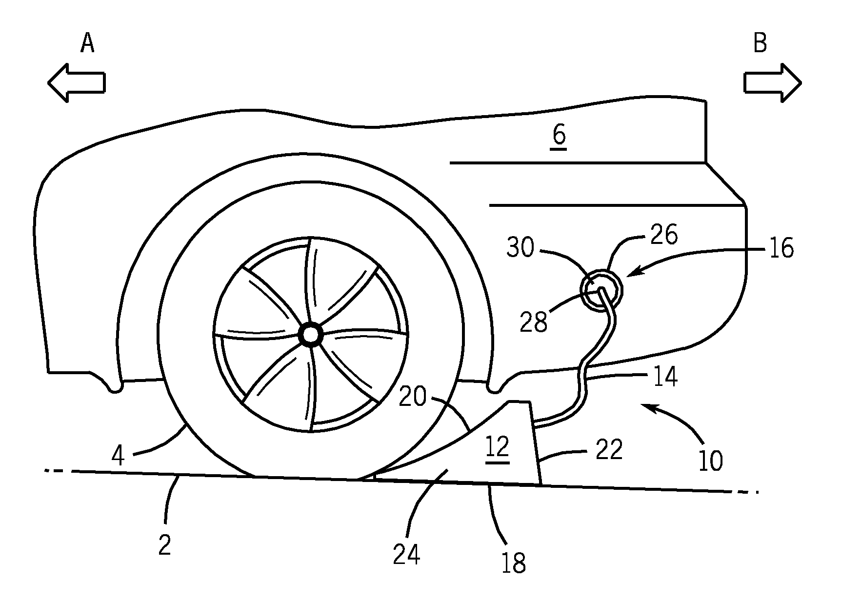
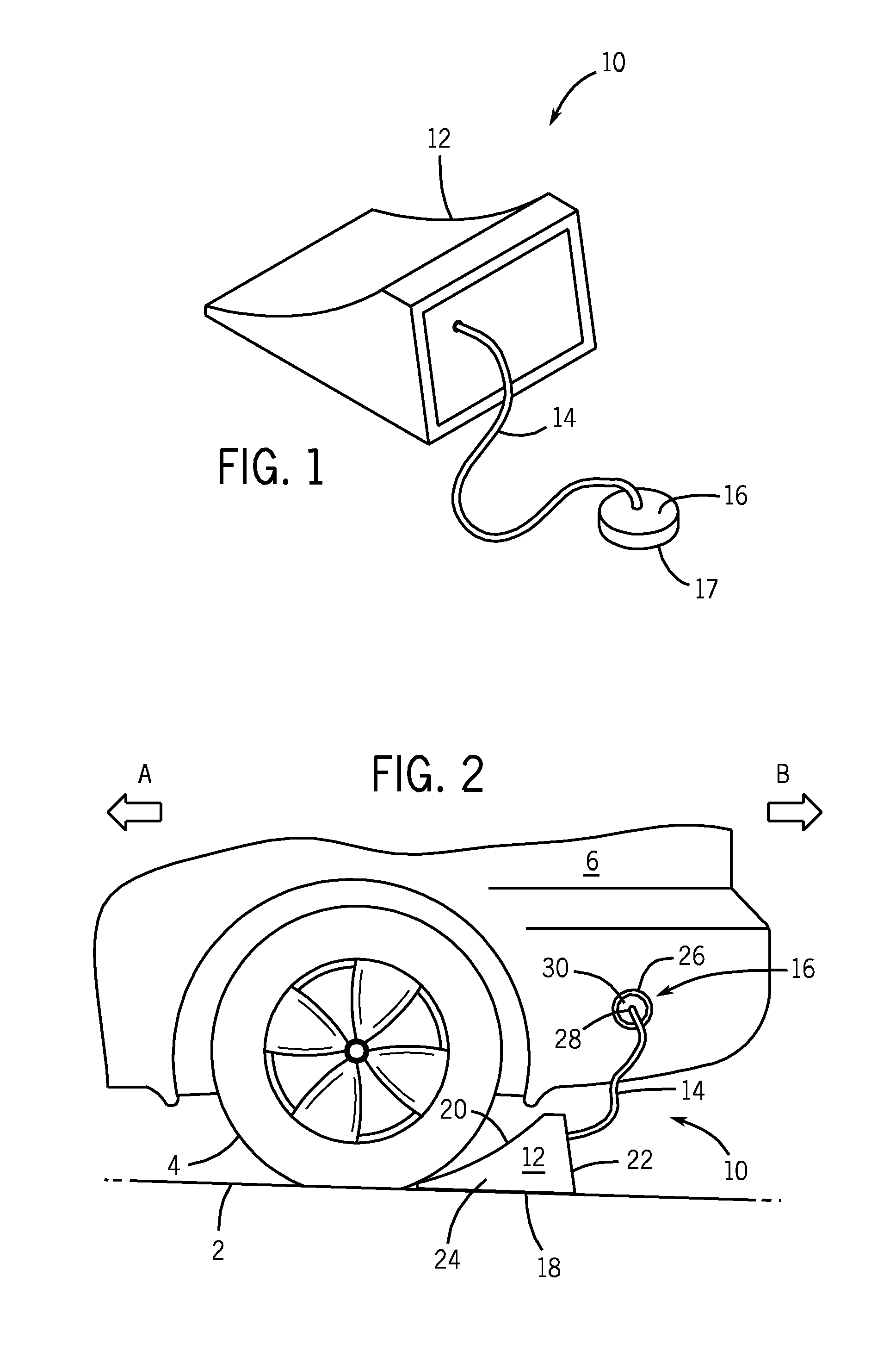
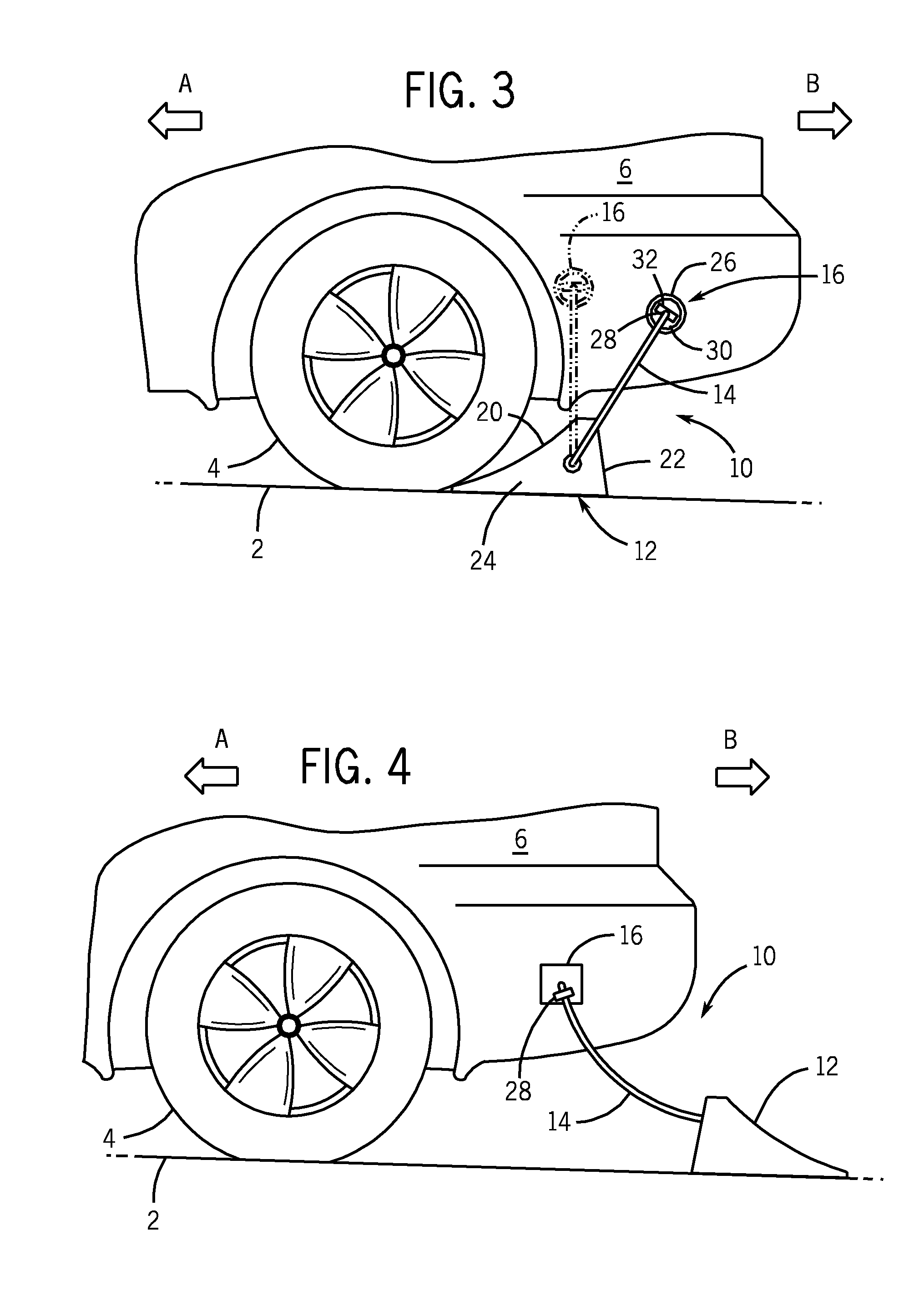
[0017]Referring initially to FIG. 1, wheel chock assembly 10 includes a wheel chock 12, a tether 14 and an attachment device 16. Tether 14 connects to chock 12 and attachment device 16. In this preferred embodiment, the first end portion of tether 14 is fastened to chock 12 and an opposing second end portion is fastened to attachment device 16.

[0018]Wheel chock 12 is a standard chock assembly 6. Wheel chock 12 has a base or first side 18, an inclined preferably arcuate ramp side 20 and a backside 22 that connects ramp side 20 and base 18. Wheel chock 12 has two opposing sides 24 that connect to base 18, ramp side 20 and backside 22. Wheel chock 12 can be fabricated from any material suitable for use as a wheel chock. This can include select polymers, metals / metal alloys, natural materials such as wood and / or composite materials.

[0019]Tether 14 is preferably a flexible line such as a rope, chain or wire that has sufficient strength to pull wheel chock 12. A first end portion of tethe...


PUM


Abstract

A wheel chock assembly is described that includes a wheel chock, a tether and an attachment device. The tether connects the wheel chock and attachment device. The wheel chock is positionable on a ground surface and against a wheel of a vehicle to block the wheel of the vehicle from rolling in a first direction. The attachment device connects to the vehicle body or chassis. When the vehicle moves in a second direction away from the wheel chock, the wheel chock is pulled beside the vehicle. The user can then stop the vehicle and remove the attachment device from the vehicle and store wheel chock assembly in a desired location in the vehicle. A method of using a wheel chock assembly includes providing a wheel chock assembly that includes a wheel chock and an attachment device connected by a tether. The wheel chock is positioned to engage the surface and wheel of the vehicle such that the wheel chock prevents the movement of the vehicle in the first direction. The attachment device is connected to the vehicle. The tether retains the connection between the attachment device and wheel chock. When the vehicle is moved in a second direction away from the wheel chock, the wheel disengages from the wheel chock. The attachment device and tether pull the wheel chock with the vehicle as it moves in the second direction.

Description

BACKGROUND OF THE INVENTION[0001]1. Field of the Invention[0002]The present disclosure relates to wheel chocks used to restrict the movement of wheeled vehicles and in particular to a wheel chock assembly that blocks the movement of the vehicle in a first direction, connects to the vehicle and the connection of the wheel chock to the vehicle removes the wheel chock from the blocked position with the movement of the vehicle in a second direction opposed to the first direction.[0003]2. Description of the Related Art[0004]Wheel chocks have the ability to provide an invaluable safety device for wheeled vehicles. The added measure of safety of wheel chocks, however, is often ignored which leads to unnecessary accidents. In many instances these accidents are associated with parking brake and / or transmission failures of the vehicle during the maintenance, repair or launching of a boat from a trailer or retrieving a boat to a trailer. These accidents can be readily prevented through the use...

Claims


Application Information

Patent Timeline
IPC IPC(8): B60T3/00B60R99/00
CPCB60T3/00B60R19/48
Inventor GIGLIO, DENIS
Owner GIGLIO DENIS
Why Eureka
Try Eureka