System and method for camera control in a surveillance system

Active Publication Date: 2012-05-17
INTERGRAH TECH CO
View PDF0 Cites 45 Cited by
  • Summary
  • Abstract
  • Description
  • Claims
  • Application Information

AI Technical Summary

Benefits of technology

[0004]Various embodiments of the present invention also include allowing the user to select at least one point in the map using the input device. The geospatial coordinates for the selected point are converted into Cartesian coordinates defined by the first coordinate system and the mathematical rotation is applied to those Cartesian coordinat

Problems solved by technology

This manual control of the camera is not very efficient, particularly if the user has a limited time period to capture and / or respond to the moving object.
These problems are further compounded if the camera is not accurately and properly mounted (e.g., to be level with the ground).
The shortcoming with this approach is that the image analysis cannot be performed unless the object is within the field of view of the camera.

Method used


Image

  • System and method for camera control in a surveillance system
  • System and method for camera control in a surveillance system
  • System and method for camera control in a surveillance system

Examples


Embodiment Construction

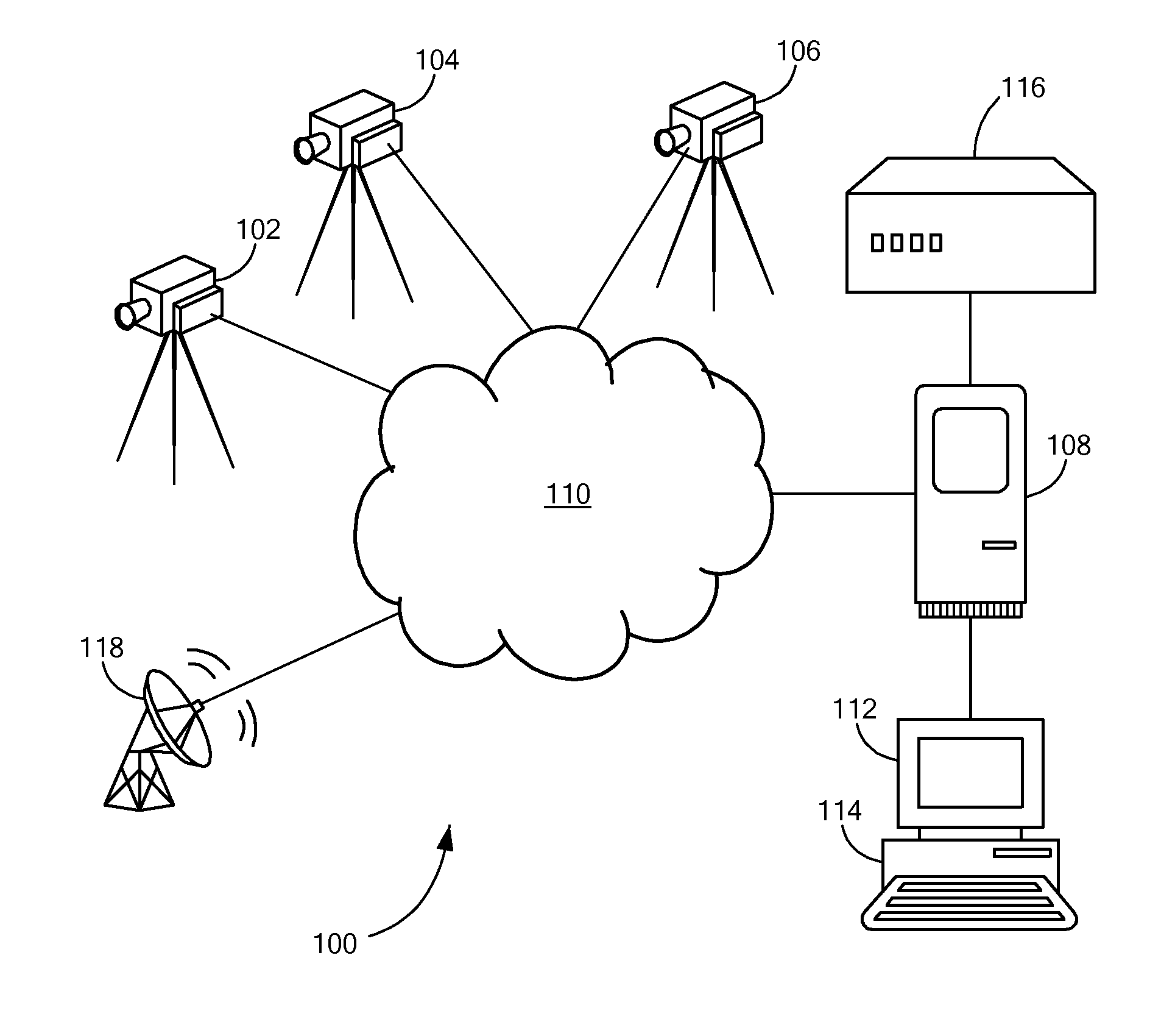
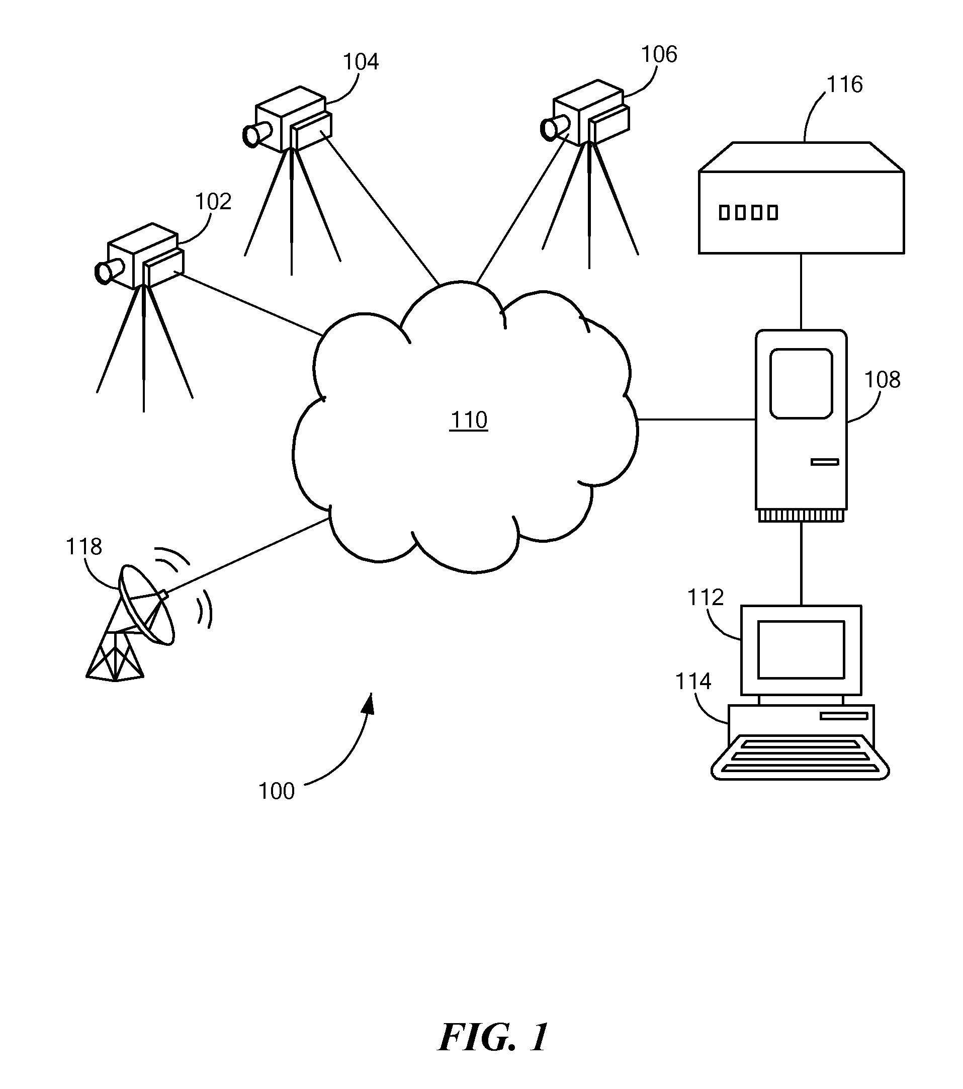
[0040]Illustrative embodiments of the present invention are directed to a surveillance system. FIG. 1 shows a surveillance system 100 in accordance with one embodiment of the present invention. Illustrative embodiments of the surveillance system include at least one camera 102. In other embodiments, such as the one shown in FIG. 1, the system includes a plurality of cameras 102, 104, 106. The cameras 102, 104, 106 are in electronic communication with a processor (e.g., a camera server) via, for example, a communications network 110. The processor 108 is also in communication with at least one display device such as a monitor 112. The display device 112 allows a user to view video feeds from the cameras 102, 104, 106. The system 100 also includes an input device 114 such as a computer mouse, a cursor, a crosshair, a keyboard, a menu, and / or a joy stick. In various embodiments, the display device 112 is also the input 114 device (e.g., touch screen). The input device 114 is in electro...


PUM


Abstract

A method and a system for calibrating a camera in a surveillance system. The method and system use a mathematical rotation between a first coordinate system and a second coordinate system in order to calibrate a camera with a map of an area. In some embodiments, the calibration can be used to control the camera and / or to display a view cone on the map.

Description

TECHNICAL FIELD[0001]The present invention relates to methods of camera control, and more particularly to methods of camera control in a surveillance system.BACKGROUND ART[0002]Surveillance systems use cameras to survey areas of interest. The cameras produce video feeds that can be displayed to a user. In this manner, the user can remotely observe an area of interest. In some cases, the cameras in the surveillance system are fixed and the user cannot change their field of view. In other cases, however, the cameras and their field of views can be adjusted through user control. Typically, the control is performed using a manual control, such as a joystick. Thus, if the video feed includes a moving object, the user manually controls the camera to follow the moving object. This manual control of the camera is not very efficient, particularly if the user has a limited time period to capture and / or respond to the moving object. These problems are further compounded if the camera is not ac...

Claims


Application Information

Patent Timeline
IPC IPC(8): G08B1/00H04N7/18
CPCG08B13/19641H04N7/181G08B13/1968
Inventor ESTES, ANDREW D.FREDERICK, JOHNNY E.
Owner INTERGRAH TECH CO
Why Eureka
Try Eureka