Beam control system for an LED luminaire

a technology of led luminaires and control systems, applied in lighting and heating equipment, lighting applications, instruments, etc., can solve the problems of color fringing of the combined mixed color output beam and/or the objection of spilling ligh

Active Publication Date: 2012-05-24
ROBE LIGHTING
View PDF3 Cites 45 Cited by
  • Summary
  • Abstract
  • Description
  • Claims
  • Application Information

AI Technical Summary

Problems solved by technology

The differently colored LEDs may be arranged in an array in the luminaire where there is physical separation between each LED, and this separation, coupled with differences in die size and placement for each color, may affect the spread of the individual colors and results in objectionable spill light and / or color fringing of the combined mixed color output beam.

Method used


Image

  • Beam control system for an LED luminaire
  • Beam control system for an LED luminaire
  • Beam control system for an LED luminaire

Examples


Embodiment Construction

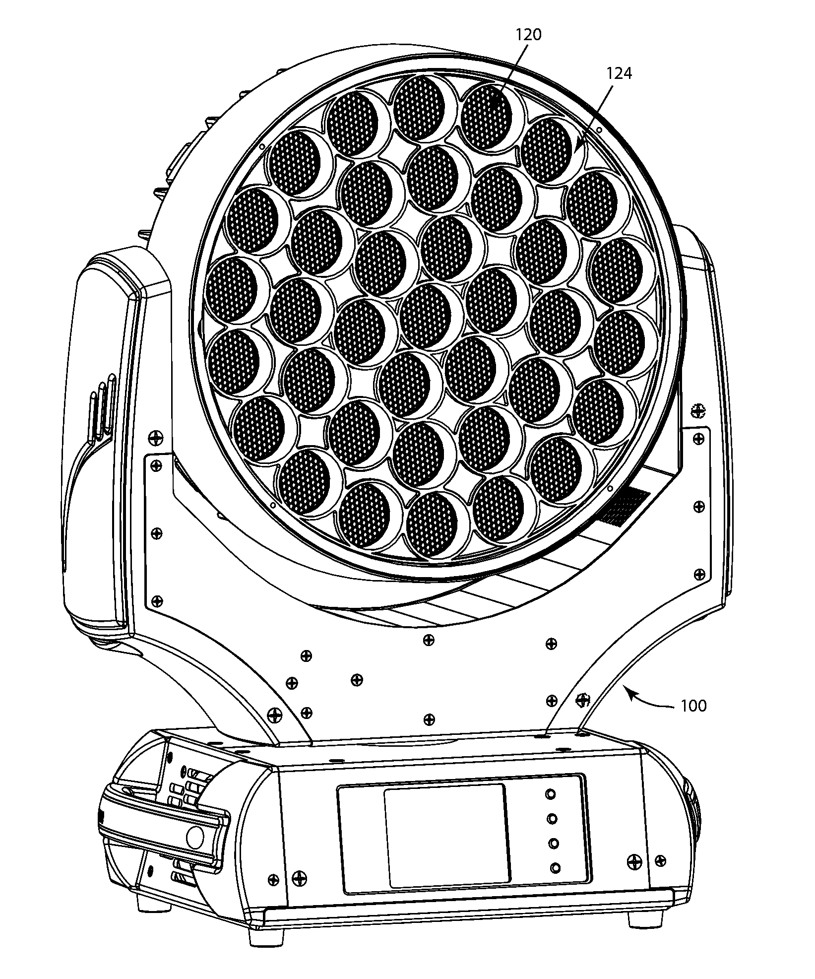
[0018]Preferred embodiments of the present invention are illustrated in the FIGURES, like numerals being used to refer to like and corresponding parts of the various drawings.

[0019]The present invention generally relates to a method for controlling the light output from an array of LEDs when used in a light beam producing luminaire, specifically to a method relating to preventing spill light and for controlling the beam angle of the array.

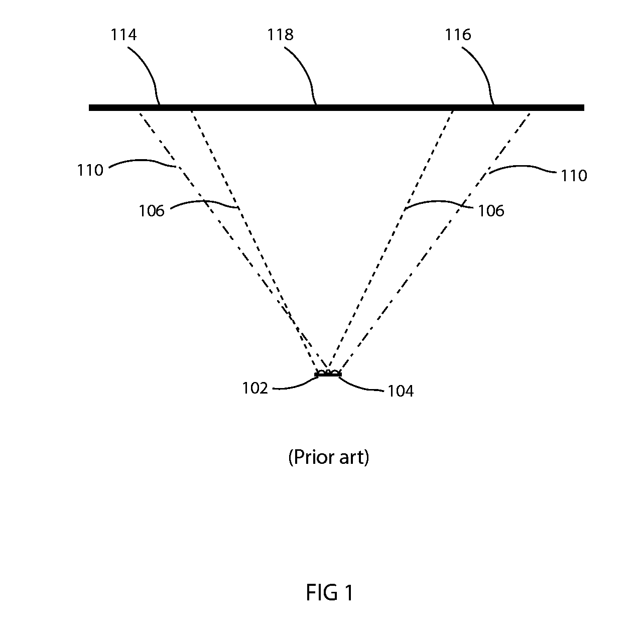
[0020]FIG. 1 illustrates a prior art system showing two LEDs as may be used in a luminaire. LED 102 and LED 104 may be of differing colors and, due to the different optical properties and construction of the LED dies, respectively produce light beams 106 and 110. These beams may differ in beam spread and position. These differences result in light beams from LEDs 102 and 104 impinging on an illuminated object 118 in such a way that areas 114 and 116 of the object are illuminated by a single LED only rather than the desired mix of both. This results...


PUM


Abstract

Described are an improved automated multi source luminaire and luminaire systems. More particularly an multicolor LED array luminaire system with a series of lenses and light louvers to control the light beam.

Description

TECHNICAL FIELD OF THE INVENTION[0001]The present invention generally relates to a method for controlling the light output from an array of LEDs when used in a light beam producing luminaire, specifically to a method relating to preventing spill light and / or for controlling the beam angle of the array.BACKGROUND OF THE INVENTION[0002]High power LEDs are commonly used in luminaires—for example in the architectural lighting industry in stores, offices and businesses as well as in the entertainment industry in theatres, television studios, concerts, theme parks, night clubs and other venues. These LEDs are also being utilized in automated lighting luminaires with automated and remotely controllable functionality. For color control it is common to use an array of LEDs of different colors. For example a common configuration is to use a mix of Red, Green and Blue LEDs. This configuration allows the user to create the color they desire by additively mixing appropriate levels of the three c...

Claims


Application Information

Patent Timeline
Patent Type & Authority Applications(United States)
IPC IPC(8): F21V5/04
CPCF21V5/008F21V13/02F21V14/06F21V14/08F21V17/02F21Y2101/02G02B2207/123F21V5/004F21W2131/406F21Y2115/10F21V11/16
Inventor JURIK, PAVELVALCHAR, JOSEF
Owner ROBE LIGHTING
Why Eureka
Try Eureka