Optical packet switching apparatus
a technology of optical packet switching and control circuit, which is applied in the direction of data switching networks, synchronisation signal speed/phase control, multiplex communication, etc., can solve the problems of difficult to perform the above-described switching control in an actual setting, and the clocks in the control circuit of the optical packet switching apparatus are not synchronised to each other, so as to improve the bandwidth usage efficiency of the transmission path.
- Summary
- Abstract
- Description
- Claims
- Application Information
AI Technical Summary
Benefits of technology
Problems solved by technology
Method used
Image

Examples
first embodiment
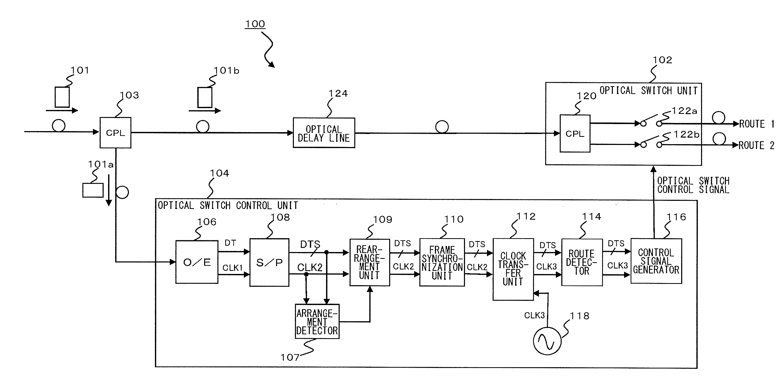
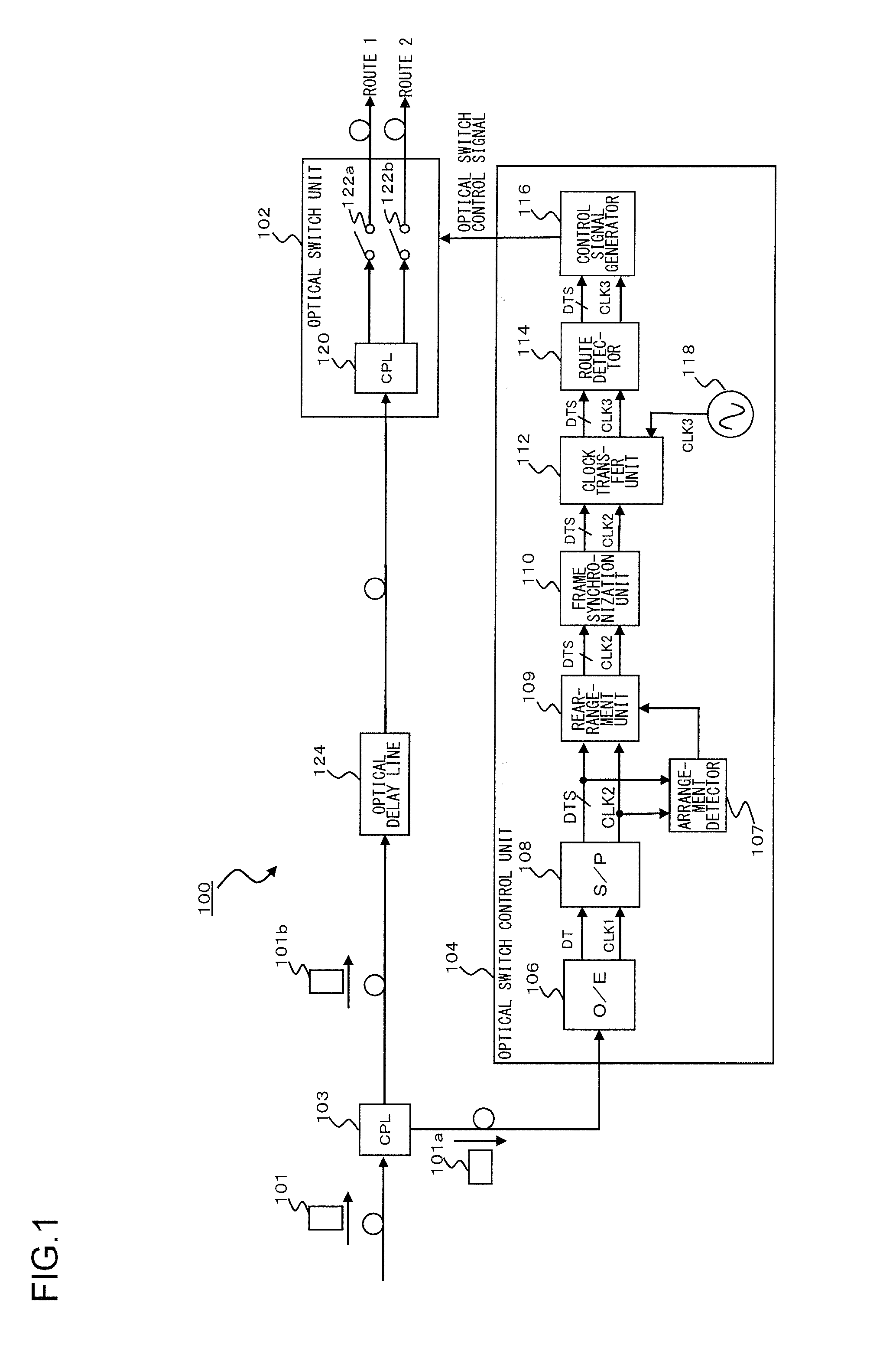
[0060]FIG. 7 is a diagram for explaining an optical packet switching apparatus 10 according to a first embodiment of the present invention. As shown in FIG. 7, the optical packet switching apparatus 10 includes an optical coupler 13, an optical switch unit 12, and an optical switch control unit 14. An optical packet signal 11 inputted to the optical packet switching apparatus 10 via a transmission path is bifurcated into two signals by the optical coupler 13. The optical packet signal may be an optical packet signal of 10 GEther or the like, for example.
[0061]An optical packet signal 11a, which is one of the bifurcated signals, is inputted to the optical switch control unit 14, whereas an optical packet signal 11b, which is the other of the bifurcated signals, is inputted to the optical switch unit 12 via an optical delay line 34. The optical switch control unit 14 extracts routing information from the optical packet signal 11a and controls the optical switch unit 12 according to th...
second embodiment
[0093]FIG. 10 is a diagram for explaining an optical packet switching apparatus 10 according to a second embodiment of the present invention. Components of the optical packet switching apparatus 10 according to the second embodiment which are identical to or correspond to those of the optical packet switching apparatus 10 according to the first embodiment shown in FIG. 7 are given the same reference numerals herein and the repeated description thereof are omitted as appropriate.
[0094]As shown in FIG. 10, the optical packet switching apparatus 10 according to the second embodiment includes a phase difference detection unit configured to detect the phase difference between a frequency-divided clock signal CLK2 inputted to the clock transfer unit 22 and a local clock signal CLK3. In the clock transfer unit 22, the frequency-divided clock signal CLK2 is a write clock, and the local clock signal CLK3 is read clock. The phase difference detection unit 29 detects the phase difference betwe...
third embodiment
[0131]FIG. 17 is a diagram for explaining an optical packet switching apparatus 10 according to a third embodiment of the present invention. Components of the optical packet switching apparatus 10 according to the third embodiment which are identical to or correspond to those of the optical packet switching apparatus 10 according to the first embodiment shown in FIG. 7 are given the same reference numerals herein and the repeated description thereof are omitted as appropriate.
[0132]The optical packet switching apparatus 10 according to the third embodiment is configured such that the first embodiment shown in FIG. 7 and the second embodiment shown in FIG. 10 are combined together. The optical packet switching apparatus 10 according to the third embodiment includes two timing adjustment units, namely a first timing adjustment unit 68 and a second timing adjustment unit 70.
[0133]As shown in FIG. 17, the arrangement information, on the arrangement of the frame synchronization patterns,...
PUM
 Abstract
Description
Claims
Application Information
 - R&D Engineer
- R&D Manager
- IP Professional
- Industry Leading Data Capabilities
- Powerful AI technology
- Patent DNA Extraction
Browse by: Latest US Patents, China's latest patents, Technical Efficacy Thesaurus, Application Domain, Technology Topic.
© 2024 PatSnap. All rights reserved.Legal|Privacy policy|Modern Slavery Act Transparency Statement|Sitemap