
Self-ligating orthodontic bracket having undercuts and related methods

Active Publication Date: 2012-05-24
ORMCO CORP
View PDF7 Cites 17 Cited by
  • Summary
  • Abstract
  • Description
  • Claims
  • Application Information

AI Technical Summary

Benefits of technology

[0014]In one embodiment, the ligating member includes a resilient ligating portion capable of flexing between an expanded position and a contracted position, and the bracket body includes a guiding track having a first portion defined by a first pair of walls and a second portion defined by a se

Problems solved by technology

But ligatures may be difficult to handle and apply so as to secure the archwire to the brackets.
The intermediate body resulting from the molding process is typically oversized compared to the final product.
Thus, the configuration of the various features of the orthodontic bracket may be limited by such a single shot molding process.
In this regard, various features of the bracket, including, for example, the archwire slot, the passageway for the ligating member, an overshoot cavity configured to capture an end of the ligating member, or other features may not be capable of being formed from a single shot molding process.
Such post-formation processes are generally time consuming and expensive.
Because the slide must be retractable from the mold cavity, or ultimately the molded body must be de-molded from the mold cavity, the slide has limited geometries.
This limitation in the single shot molding process then limits the possible geometries of the bracket features capable of being formed by such movable slides.
For example, certain undercut formations, which include various voids or cavities, are not capable of being formed in a single shot molding process and thus are typically formed using post-formation processes.

Method used


Image

  • Self-ligating orthodontic bracket having undercuts and related methods
  • Self-ligating orthodontic bracket having undercuts and related methods
  • Self-ligating orthodontic bracket having undercuts and related methods

Examples


Embodiment Construction

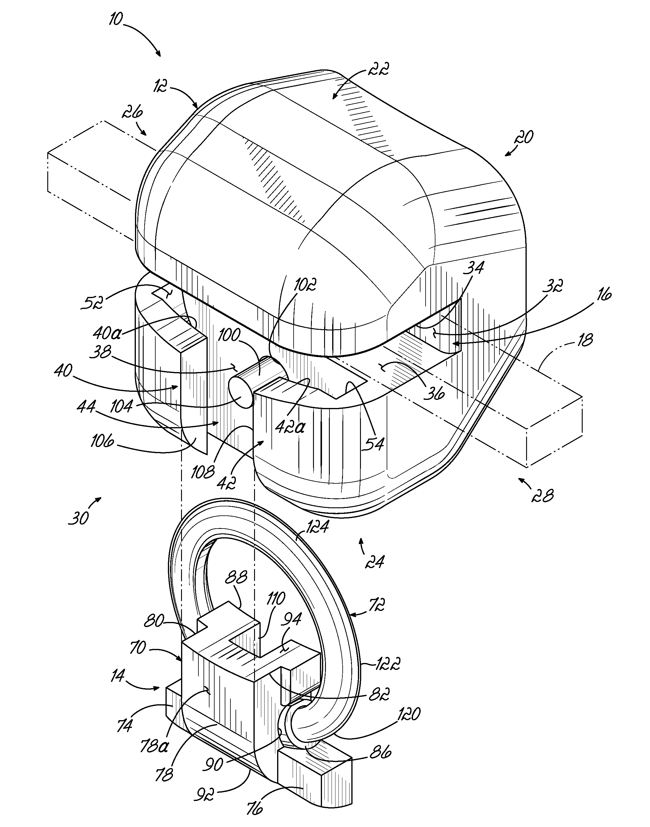
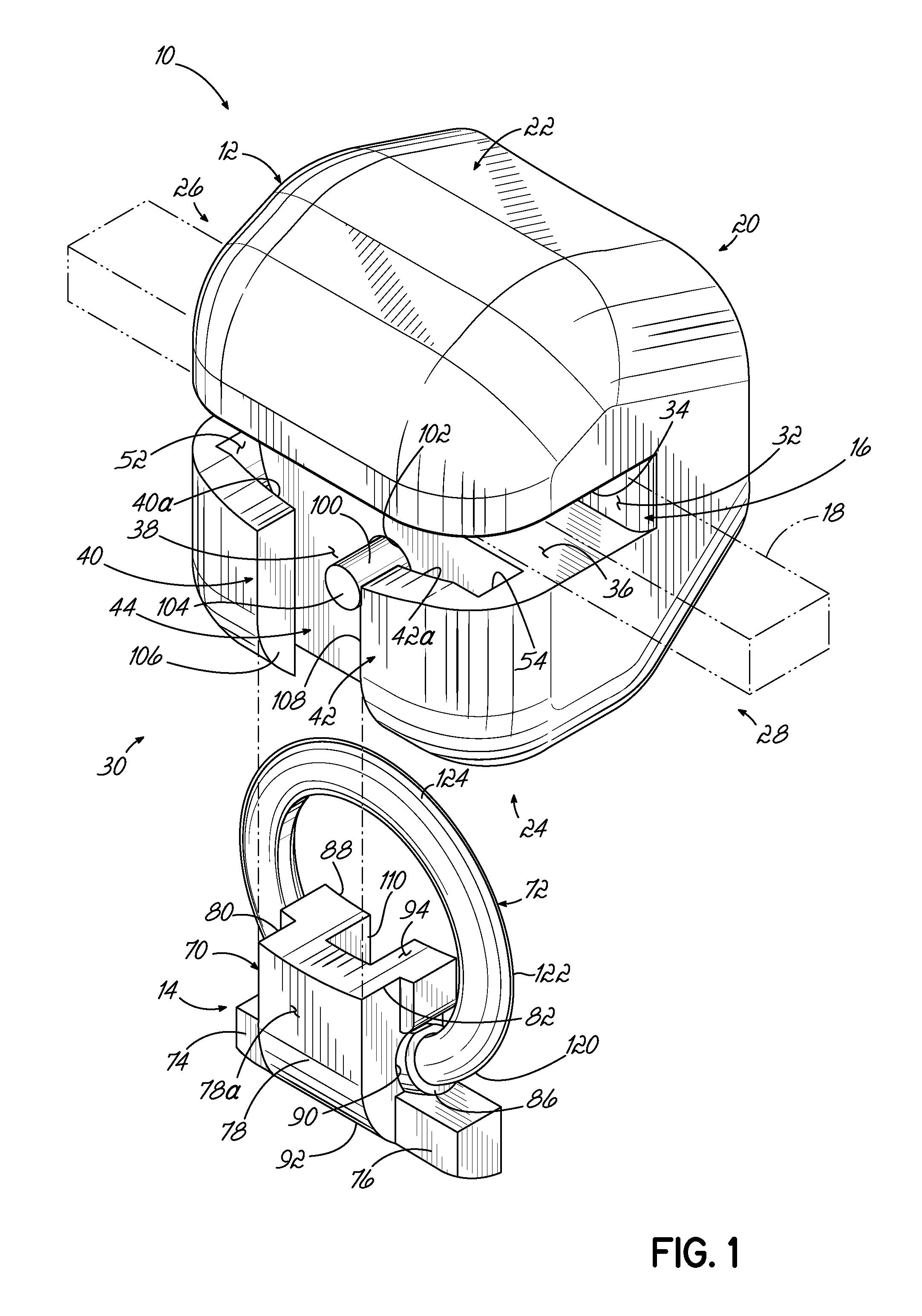
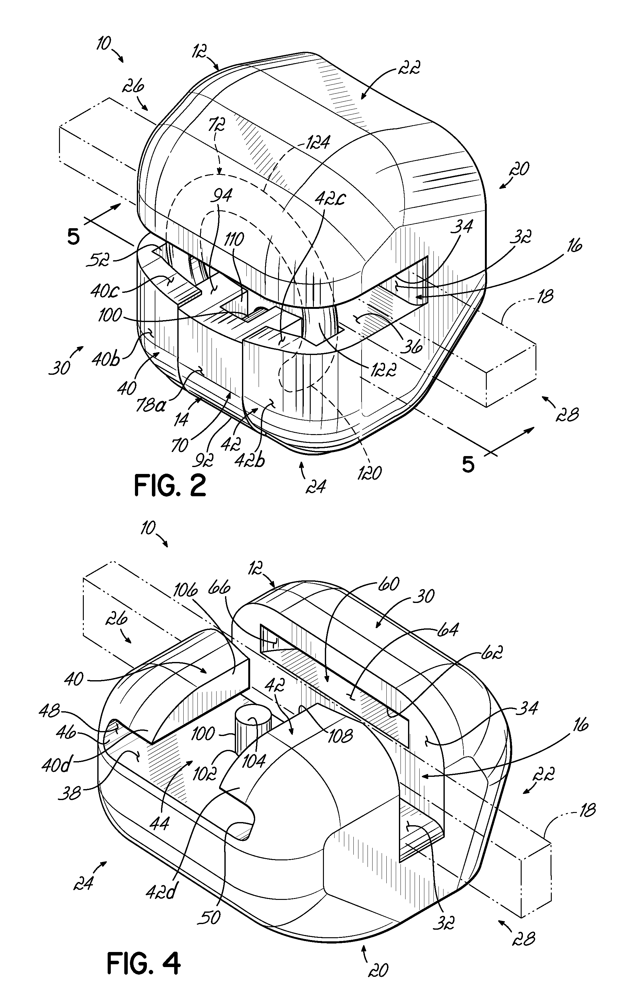
[0028]Referring now to the drawings and specifically to FIGS. 1-5, an exemplary orthodontic bracket 10 includes a bracket body 12 and a ligating member 14 that engages with the bracket body 12. In this embodiment, the ligating member 14 is slidable relative to the bracket body 12. The bracket body 12 includes an archwire slot 16 formed therein which is adapted to receive an archwire 18 (shown in phantom) for applying corrective forces to the teeth. The ligating member 14 slides relative to the bracket body 12 between an opened position (FIG. 3) in which the archwire 18 is insertable into the archwire slot 16, and a closed position (FIG. 2) in which the ligating member 14 overlies the archwire slot 16 and retains the archwire 18 therein. As will be described in more detail below, the orthodontic bracket 10, and more particularly the bracket body 12 thereof, is formed through a molding process and includes a number of features which otherwise cannot be formed through the single shot m...


PUM


Abstract

A method of manufacturing an orthodontic appliance may include molding a plurality of green bodies in plurality of molds and coupling the green bodies so as to form an intermediate green body. The orthodontic appliance may be an orthodontic bracket body. The plurality of green bodies may be molded so as to be devoid of any undercut formations. Coupling the plurality of green bodies may form the intermediate green body to include at least one undercut formation. An orthodontic bracket may include an undercut formation not capable of being formed in a single shot molding process and not formed through post-formation processes. The undercut formation may include a guiding track and / or a retaining recess configured to receive a portion of the ligating member. The ligating member may include a flexible ligating portion that overlies the archwire slot and a relatively rigid main body portion.

Description

CROSS REFERENCE TO RELATED CASES[0001]This application claims priority to U.S. Provisional Patent Application Ser. No. 61 / 416,922 filed Nov. 24, 2010, the disclosure of which is incorporated by reference herein in its entirety.TECHNICAL FIELD[0002]The present invention relates generally to orthodontic brackets and, more specifically, to self-ligating orthodontic brackets having undercuts and methods for making orthodontic brackets having such undercuts.BACKGROUND[0003]Orthodontic brackets are a component of orthodontic systems for correcting malpositioned teeth. Orthodontic treatment using such systems generally involves the application of mechanical forces to urge malpositioned teeth into correct alignment. In conventional treatment, orthodontists or their assistants affix orthodontic brackets to a patient's teeth and engage an archwire into an archwire slot in each bracket. The archwire applies mechanical forces that coerce the teeth to move into a desired position. Traditionally,...

Claims


Application Information

Patent Timeline
IPC IPC(8): A61C7/30B32B38/16A61C7/28
CPCA61C7/287A61C7/30
Inventor ODA, TODD I.
Owner ORMCO CORP
Learn More