Multi Channel LED Driver

a technology of led drivers and led drivers, applied in the direction of instruments, light sources, electrical equipment, etc., can solve the problems of unsatisfactory high losses of the above-mentioned current regulators

Active Publication Date: 2012-05-31
INFINEON TECH AG
View PDF2 Cites 101 Cited by
  • Summary
  • Abstract
  • Description
  • Claims
  • Application Information

AI Technical Summary

Benefits of technology

[0023]Although various exemplary embodiments of the invention have been disclosed, it will be apparent to those skilled in the art that various changes and modifications can be made which will achieve some of the advantages of the invention without departing from the spirit and scope of the invention. It will be obvious to those reasonably skilled in the art that other components performing the same functions may be suitably substituted. It should be mentioned that features explained with reference to a specific figure may be combined with features of other figures, even in those where not explicitly been mentioned. Further, the methods of the invention may be achieved in either all software implementations, using the appropriate processor instructions, or in hybrid implementations that utilize a combination of hardware logic and software logic to achieve the same results. Such modifications to the inventive concept are intended to be covered by the appended claims.

Problems solved by technology

Such a design entails undesirably high losses in the above-mentioned current regulators.

Method used


Image

  • Multi Channel LED Driver
  • Multi Channel LED Driver
  • Multi Channel LED Driver

Examples


Embodiment Construction

[0011]The making and using of the presently preferred embodiments are discussed in detail below. It should be appreciated, however, that the present invention provides many applicable inventive concepts that can be embodied in a wide variety of specific contexts. The specific embodiments discussed are merely illustrative of specific ways to make and use the invention, and do not limit the scope of the invention.

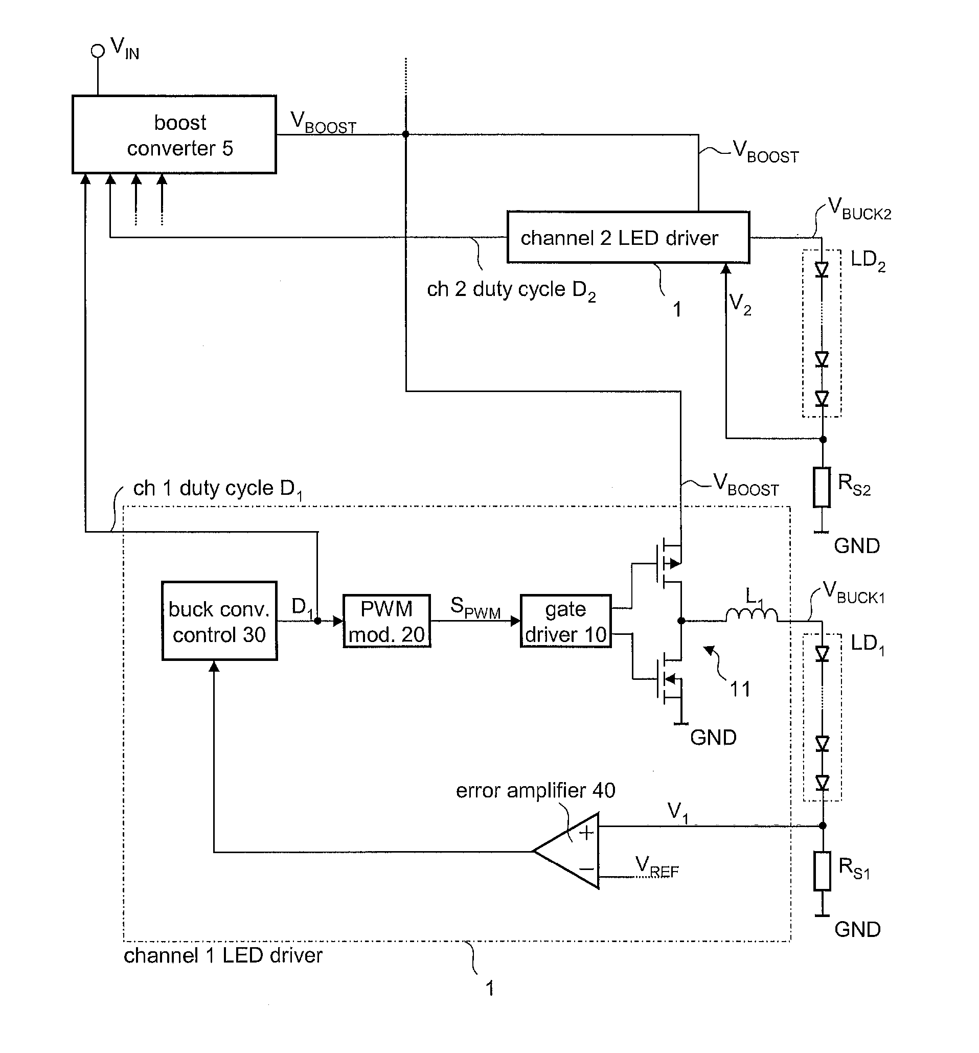
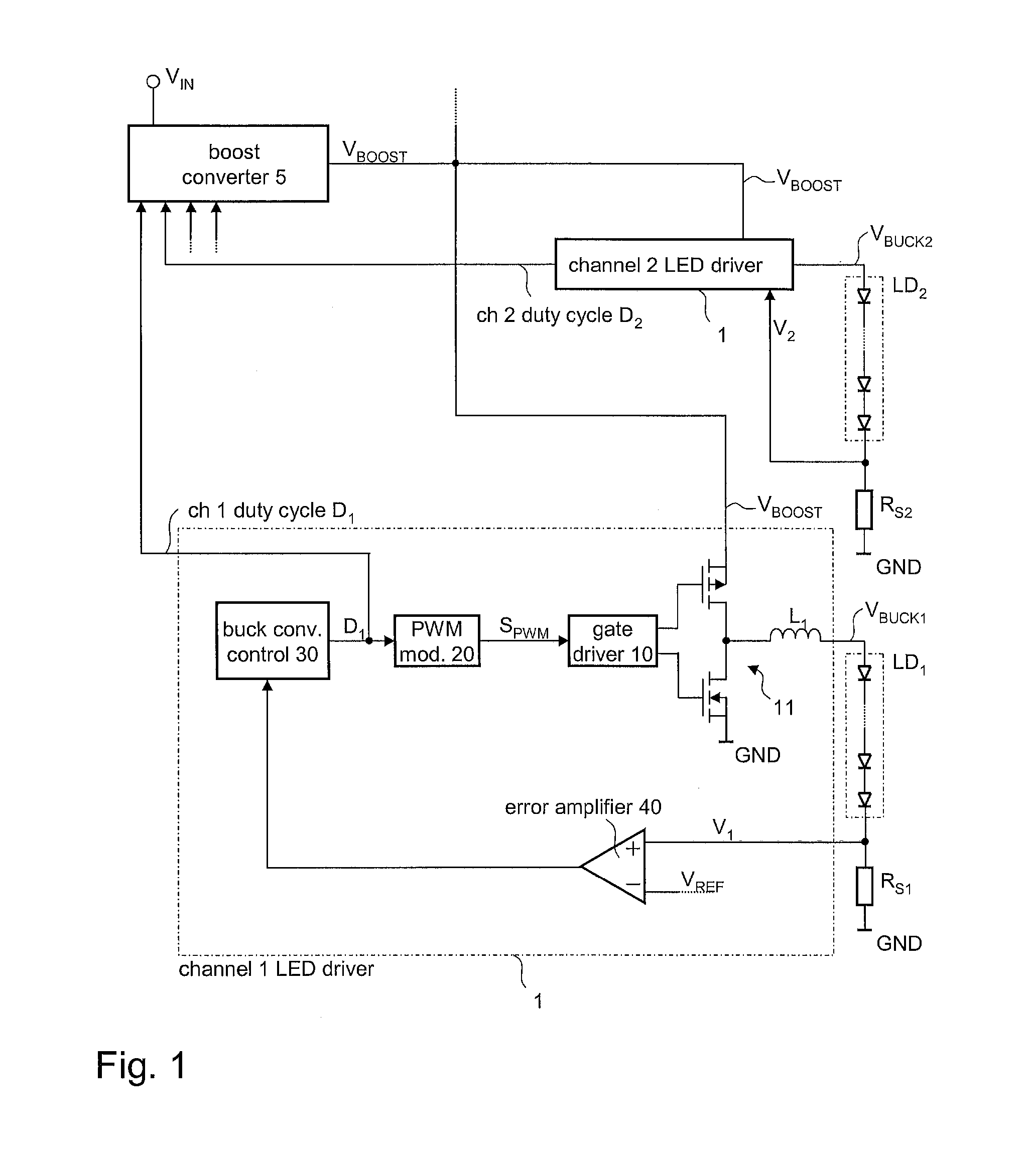
[0012]FIG. 1 illustrates a LED driver circuit in accordance with a first embodiment of the present invention. The driver circuit is able to provide defined load currents to a plurality of LED chains LD1, LD2, etc., connected to the driver circuit. To provide the load currents to the LED chains LD1, LD2 the driver circuits include buck converters 1, wherein each LED chain is connected to the output of a corresponding buck converter 1 of the driver circuit. The buck converters 1 receive common input voltage VBOOST provided by a switching converter 5 which is, in the present exa...


PUM


Abstract

A driver circuit includes a buck converter associated with each LED chain for supplying a load current thereto. The buck converter receives an input voltage and is configured to provide a supply voltage to the associated LED chain such that the resulting load current of the LED chain matches at least approximately a predefined reference current value. The driver circuit further includes a switching converter that receives a driver supply voltage from a power supply and provides, as an output voltage, the input voltage for the buck converters. The switching converter is configured to provide an input voltage to the buck converters such that the maximum of the ratios between the input voltage and the supply voltages provided to the LED chains matches a predefined tolerance reference ratio.

Description

TECHNICAL FIELD[0001]The invention generally relates to driver circuitry, in particular, to circuitry configured to drive illumination devices based on light emitting diodes (LEDs).BACKGROUND[0002]As light emitting diodes (LEDs) are increasingly used for illumination purposes, in particular, as a substitute for light bulbs, adequate driver circuitry has been subject to research and development in recent times. Inter alia, one desired object of such development efforts is to increase efficiency, that is to reduce power dissipation in the driver circuitry. Other development goals include, an increased flexibility of use and low costs.[0003]One LED based illumination device usually includes a series circuit of a plurality of LEDs, a so-called LED chain. As LEDs usually have to be driven by a defined current, each LED in a LED chain is supplied with a fixed (not necessarily the same for all the LED chains) current. The supply voltage, necessary for driving the LED chain depends on the n...

Claims


Application Information

Patent Timeline
Patent Type & Authority Applications(United States)
IPC IPC(8): H05B41/36
CPCH05B33/0857H05B33/0827H05B45/325H05B45/38H05B45/39H05B45/46
Inventor CAPODIVACCA, GIOVANNICORTIGIANI, FABRIZIOSCENINI, ANDREA
Owner INFINEON TECH AG
Why Eureka
Try Eureka