Fuse assembly
- Summary
- Abstract
- Description
- Claims
- Application Information
AI Technical Summary
Benefits of technology
Problems solved by technology
Method used
Image
Examples
first embodiment
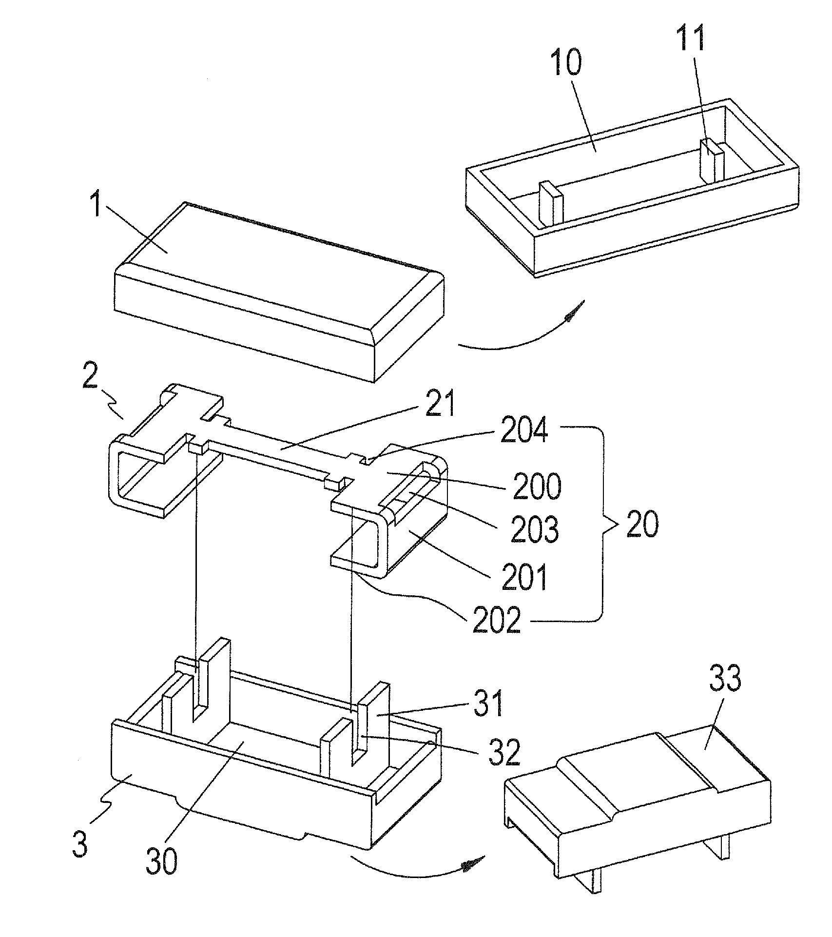
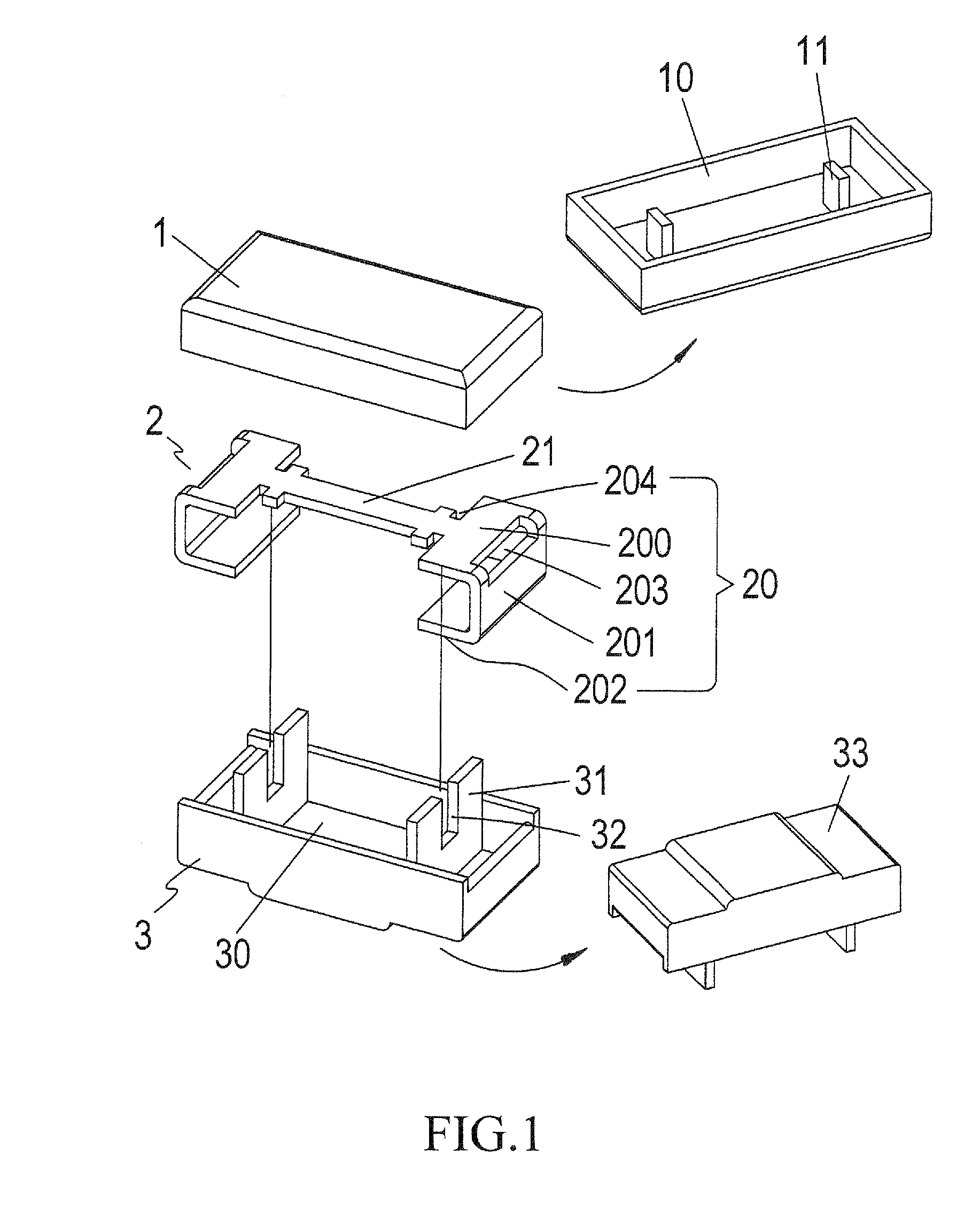
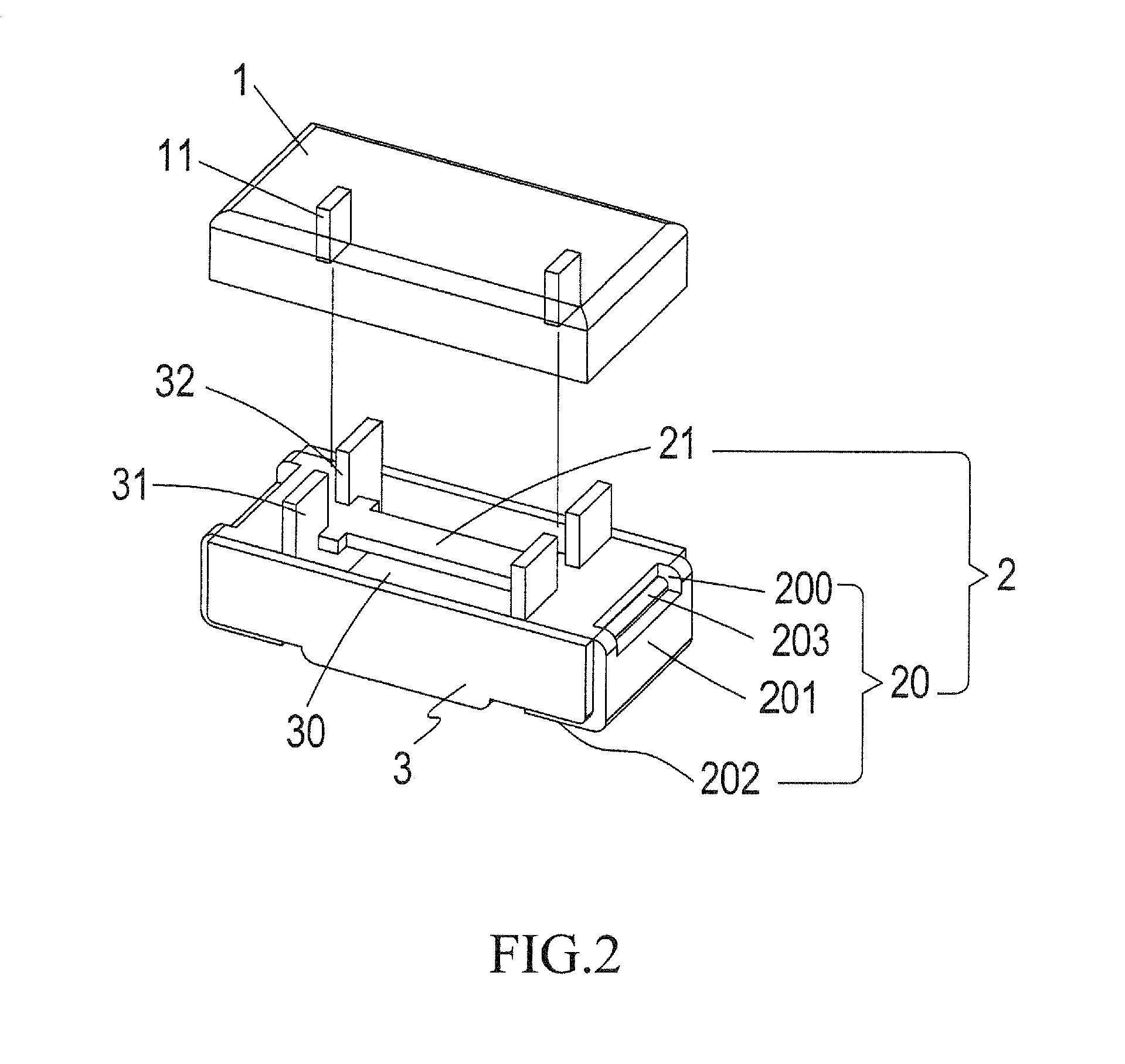
[0019]As shown in FIG. 1, a fuse assembly according to the present invention contains a first casing member 1, a disconnection member 2, and a second casing member 3.
[0020]The first casing member 1 is a cover forming a first chamber 10 with an open bottom. Inside the first chamber 10, there are two parallel, opposing, and downward extending pressing pieces 11.
[0021]The disconnection member 2 contains two electrodes 20 and a fuse element 21 between the two electrodes 20. Each electrode 20 contains a first lateral section 200, a vertical section 201, and a second lateral section 202, jointly and integrally forming a C-like shape. The electrodes 20's C-shapes face each other. A notch 203 is provided along the right-angled junction between the first lateral section 200 and the vertical section 201. At the junction between each end of the fuse element 21 and the first lateral section 200 of an electrode 20, two opposing slits 204 are provided, thereby forming a neck section between the f...
third embodiment
[0028]FIG. 7 depicts a fuse assembly according to the present invention. As illustrated, the first casing member 50 is a cover forming a first chamber with an open bottom, while the second casing member 51 is a box forming a second chamber 52 with an open top. Inside the second chamber 52, there are a number of upward extending positioning pins 53. On a bottom side of the second casing member 51, there are two indentations 54 along its lateral ends, respectively.
[0029]The disconnection member 6 contains two electrodes 60 and a fuse element 61 between the two electrodes 60. Each electrode 60 contains a first lateral section 600, a vertical section 601, and a second lateral section 602, jointly and integrally forming a C-like shape. On the first lateral section 600 of each electrode 60, there are a number of positioning holes 603.
[0030]As in the previous embodiments, the disconnection member 6 is positioned between the first and second casing members 50 and 51, and the fuse element 61...
fourth embodiment
[0031]FIG. 8 depicts a fuse assembly according to the present invention. As illustrated, the first casing member 70 is a cover forming a first chamber 71 with an open bottom, while the second casing member 72 is a box forming a second chamber 73 with an open top.
[0032]The disconnection member 8 contains two electrodes 80 and a fuse element 81. Each electrode 80 contains a first lateral section 800, a vertical section 801, and a second lateral section 802, jointly and integrally forming a C-like shape. The two ends of the fuse element 81 are connected to the first lateral sections 800 of the electrodes 80, respectively. The fuse element 81 is preferably a fuse filament.
[0033]As in the previous embodiments, the disconnection member 8 is positioned between the first and second casing members 70 and 72, and the fuse element 8 is housed in an enclosed space formed by the first and second casing members 70 and 72. Each electrode 80's C shape wraps around a lateral side of the second casin...
PUM
 Abstract
Description
Claims
Application Information
 - R&D
- Intellectual Property
- Life Sciences
- Materials
- Tech Scout
- Unparalleled Data Quality
- Higher Quality Content
- 60% Fewer Hallucinations
Browse by: Latest US Patents, China's latest patents, Technical Efficacy Thesaurus, Application Domain, Technology Topic, Popular Technical Reports.
© 2025 PatSnap. All rights reserved.Legal|Privacy policy|Modern Slavery Act Transparency Statement|Sitemap|About US| Contact US: help@patsnap.com


