Light source device and projection display apparatus

a technology of projection display and light source device, which is applied in the direction of lighting and heating apparatus, instruments, spectral modifiers, etc., can solve the problems of low reliability, difficult configuration, and inability to achieve high brightness in fig. 10

Active Publication Date: 2012-05-31
PANASONIC CORP
View PDF7 Cites 128 Cited by
  • Summary
  • Abstract
  • Description
  • Claims
  • Application Information

AI Technical Summary

Benefits of technology

[0016]According to the light source device of the above-described configuration, since respective columns of the solid-state light sources aligned in the z-axis direction in a pair of opposed solid-state light source units are arranged alternately in the y-axis direction, and the density of exiting light beams from the solid-state light sources is increased in the x-axis direction by the reflection unit, it is possible to condense and combine light from a plurality of solid-state light sources efficiently and configure a bright, compact light source device.
[0017]According to the projection display apparatus of the above-described configuration, by using the light source device of the present invention, it is possible to configure a long-life, bright projection display apparatus.

Problems solved by technology

However, since the discharge lamp has the problem of a short life, the reliability is low.
Because of this, it is difficult for the configuration shown in FIG. 10 to obtain high brightness.
Therefore, as the number of the solid-state light source increases, an outline of exiting light beams becomes larger, which increases the size of the light source device.

Method used


Image

  • Light source device and projection display apparatus
  • Light source device and projection display apparatus
  • Light source device and projection display apparatus

Examples


embodiment 1

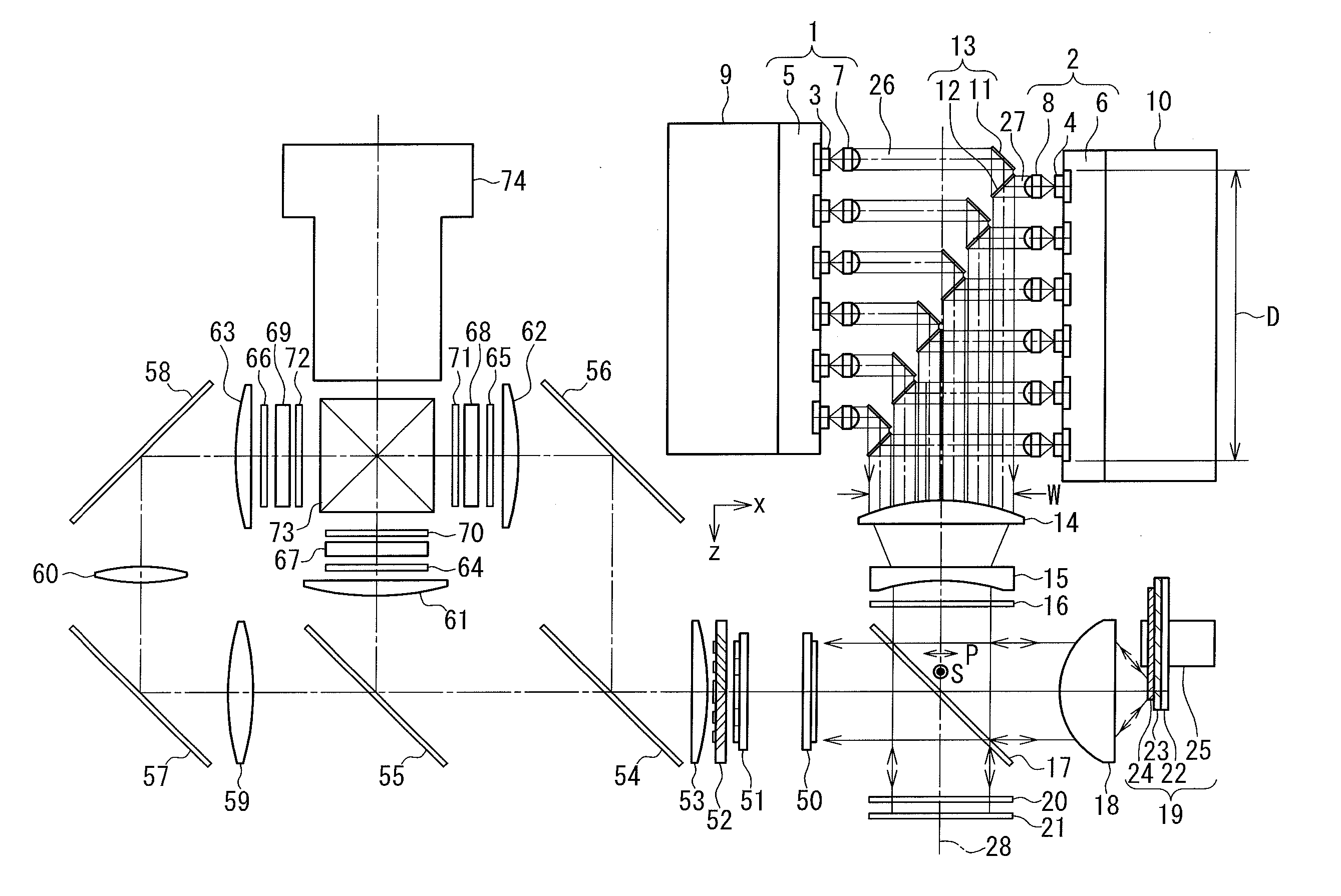
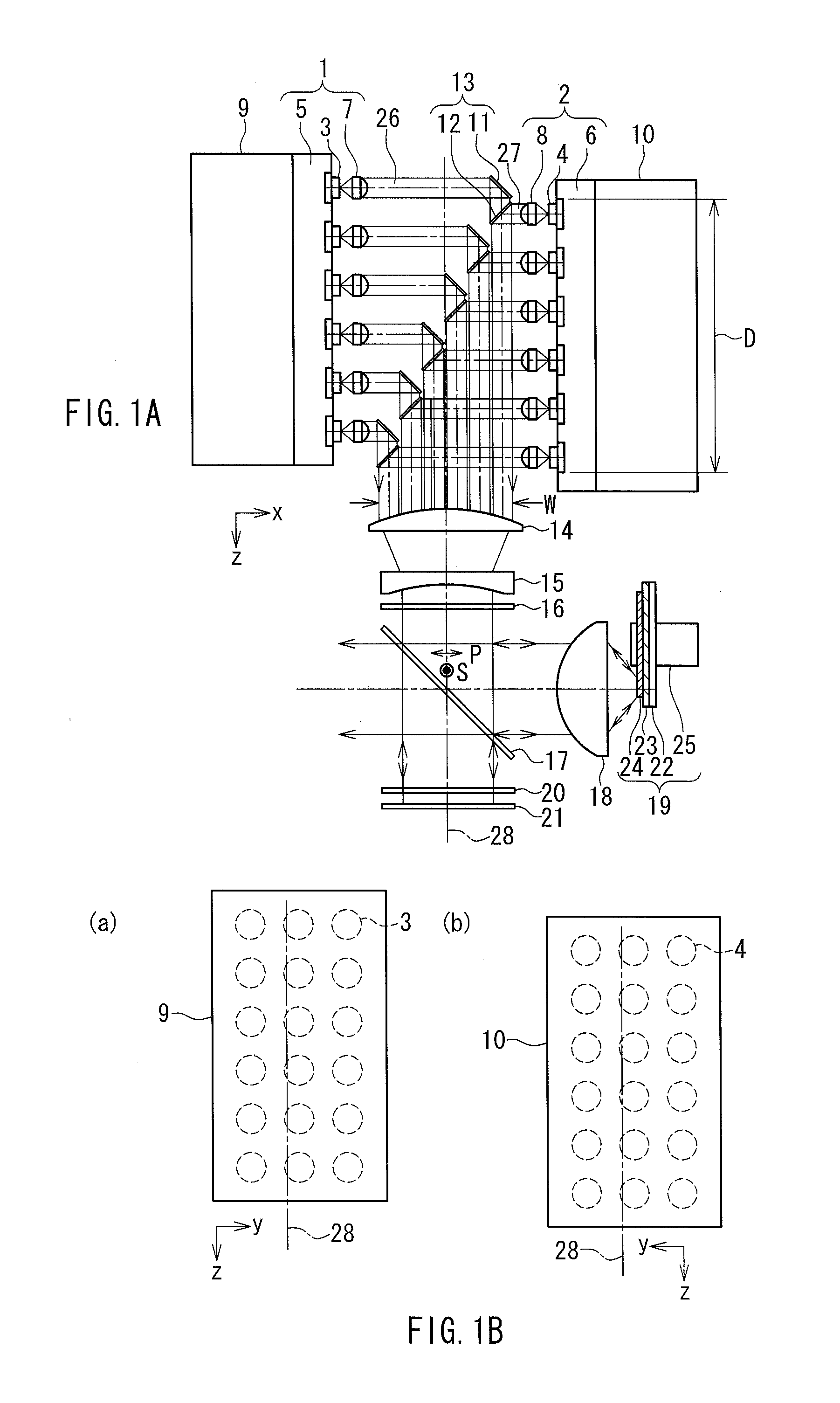
[0046]FIG. 1A is a front view showing a configuration of a light source device according to Embodiment 1 of the present invention. The light source device has a characteristic of efficiently condensing and combining light beams from a plurality of semiconductor lasers contained in a pair of first and second solid-state light source units 1, 2 that are disposed opposite to each other, with a compact configuration.

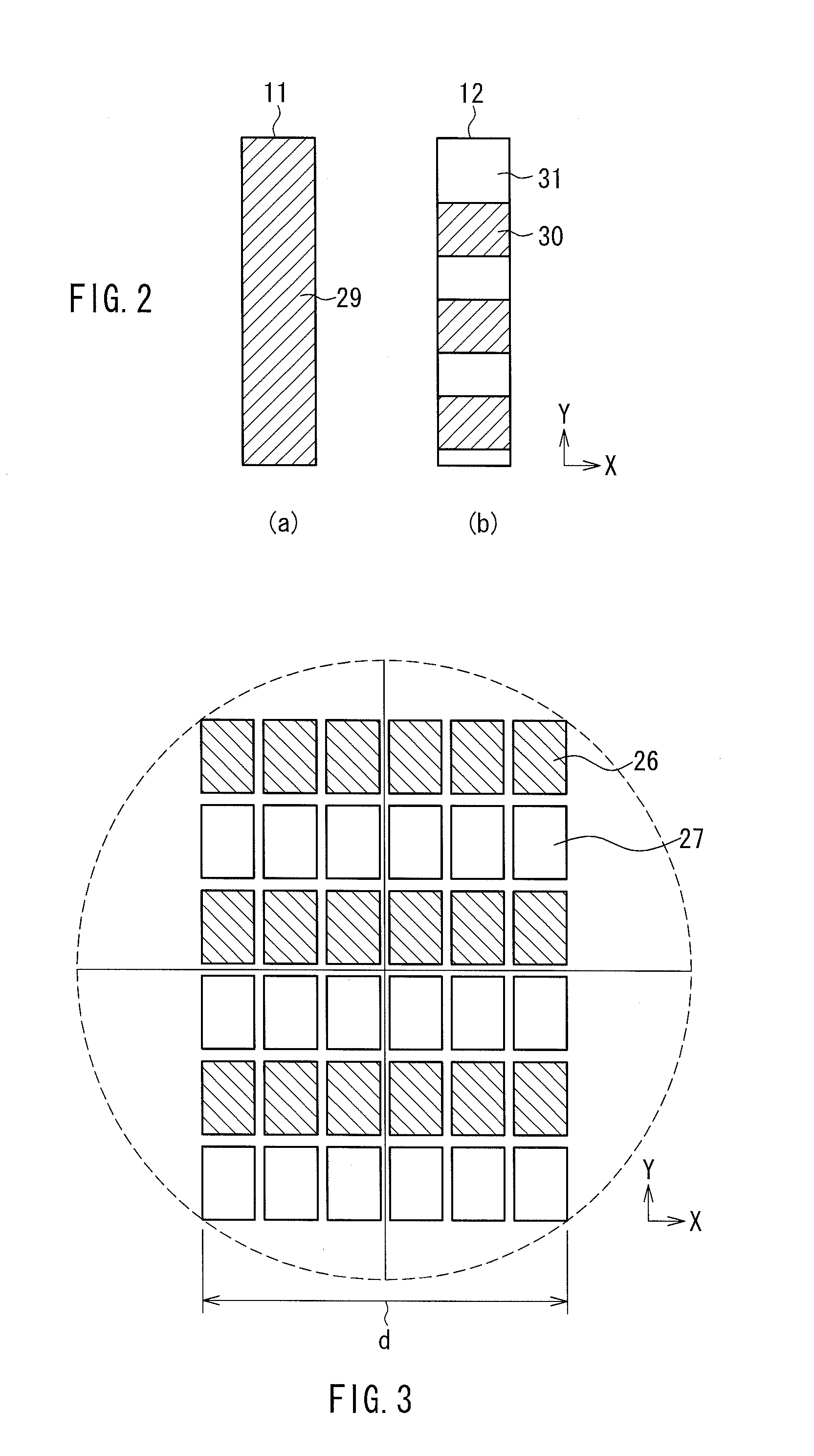
[0047]The first and second solid-state light source units 1, 2 include blue semiconductor lasers 3, 4, heat-dissipation plates 5, 6, and condensing lenses 7, 8, respectively. The heat-dissipation plates 5, 6 are equipped with heat sinks 9, 10, respectively. A reflection unit 13 composed of total-area reflection mirrors 11 and partial-area reflection mirrors 12 are provided between the first and second solid-state light source units 1, 2, thereby reflecting light beams from the semiconductor lasers 3, 4 in one direction.

[0048]A first condensing part composed of lenses 14, 15,...

embodiment 2

[0068]FIG. 6 is a front view showing a configuration of a light source device in Embodiment 2 of the present invention. The light source device includes two solid-state light source units, i.e., first and second solid-state light source units 40, 41, which have the same configuration as those of Embodiment 1, and have substantially the same configuration as the light source device of Embodiment 1. Therefore, the same elements as those in Embodiment 1 are given the same reference numerals, and the repeated descriptions will be omitted. The configuration of the present embodiment is different from that of Embodiment 1 in that, as blue color light to be combined for obtaining white light, blue color light of a light-emitting diode is used in place of exiting light from semiconductor lasers 42, 43.

[0069]In the configuration of FIG. 6, light entering a dichroic mirror 44 from the first and second solid-state light source units 40, 41 is polarized in one direction. In other words, the sem...

embodiment 3

[0077]FIG. 7 shows a projection display apparatus in Embodiment 3 of the present invention. This projection display apparatus makes use of the light source device in Embodiment 1. Therefore, elements of the light source device are given the same reference numerals as those in Embodiment 1, and the repeated descriptions will be omitted.

[0078]In the present embodiment, as a light valve, an active-matrix type transmission-type liquid crystal panel is used. A mode thereof is TN or VA and a thin-film transistor is formed in a pixel region.

[0079]An illumination portion for condensing exiting light from the dichroic mirror 17 so as to form illumination light is composed of first and second lens array plates 50, 51, a polarization converting optical element 52 and a superimposing lens 53. A color separation portion for color-separating the illumination light having passed through the superimposing lens 53 and allowing the separated color lights to enter liquid crystal light valves for the r...


PUM


Abstract

A light source device includes: first and second solid-state light source units disposed opposite to each other, each unit including solid-state light sources; a reflection unit; a condensing part; and a fluorescence emission plate excited with a condensed light beam. The light sources in each of the units are arranged two-dimensionally with the optical axes oriented in an x-axis direction. Each column of the light sources of the first and the second light source units are arranged alternately in the y-axis direction. The reflection unit reflects the light beams from the light source units in the z-axis direction so as to be arranged into a two-dimensional array in a xy plane. A density of the reflected light beams in the x-axis direction is higher than that of the arrangement of the light sources in the z-axis direction. Light from solid-state light sources are condensed and combined efficiently, with a compact configuration.

Description

BACKGROUND OF THE INVENTION[0001]1. Field of the Invention[0002]The present invention relates to a light source device configured to combine light from a plurality of solid-state light sources so as to excite a phosphor, and a projection display apparatus illuminating an image on a light valve with illumination light from the light source device so as to magnify and project the image.[0003]2. Description of Related Art[0004]A discharge lamp has been used widely as a light source of a projection display apparatus that uses a light valve composed of a liquid crystal or a mirror-deflection type digital micromirror device (DMD). However, since the discharge lamp has the problem of a short life, the reliability is low. Therefore, in order to solve this problem, recently, solid-state light sources such as a semiconductor laser and a light-emitting diode have been studied for use as the light source of the projection display apparatus.[0005]FIG. 10 shows a configuration disclosed in JP 200...

Claims


Application Information

Patent Timeline
Patent Type & Authority Applications(United States)
IPC IPC(8): G03B21/28F21V9/16
CPCG03B21/2013G03B21/2066G03B21/204
Inventor TANAKA, TAKAAKI
Owner PANASONIC CORP
Why Eureka
Try Eureka