Vehicle mirror apparatus

Active Publication Date: 2012-05-31
KK TOKAI RIKA DENKI SEISAKUSHO
View PDF1 Cites 9 Cited by
  • Summary
  • Abstract
  • Description
  • Claims
  • Application Information

AI Technical Summary

Benefits of technology

[0030]In this aspect, the connection portions connect together the plural radial direction stopper portions. Reinforcement of the radial direction stopper portion

Problems solved by technology

This leads to the possibility of operation noise of the mirror-face adjusting actuator ge

Method used


Image

  • Vehicle mirror apparatus
  • Vehicle mirror apparatus
  • Vehicle mirror apparatus

Examples


Embodiment Construction

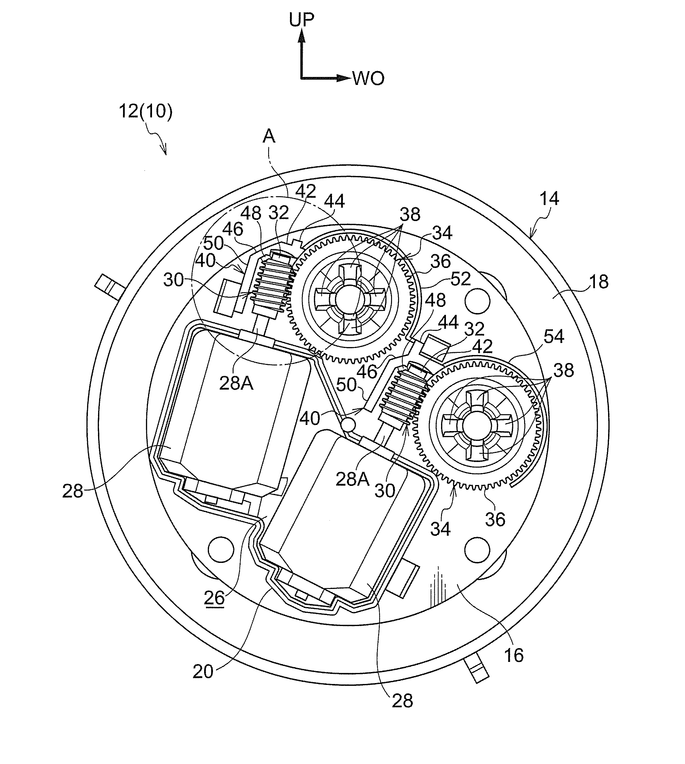
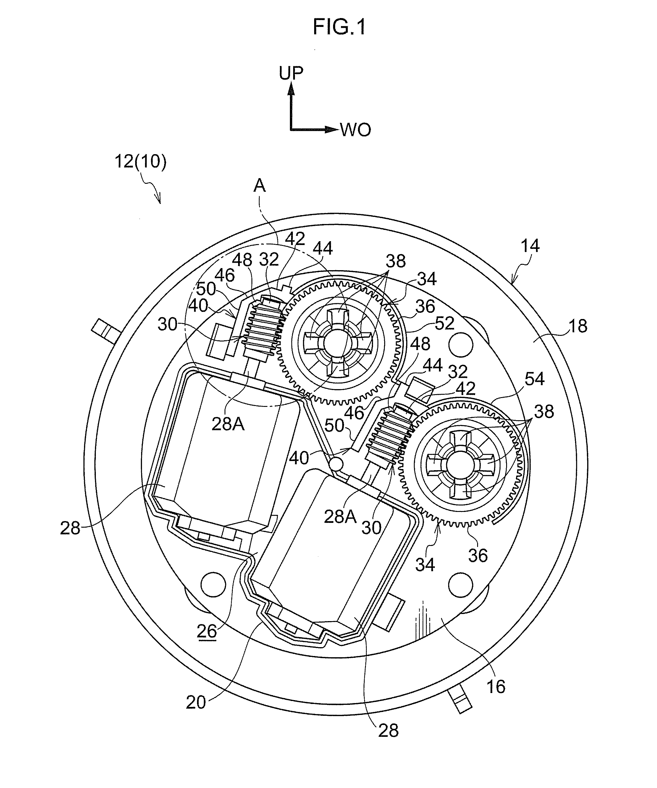
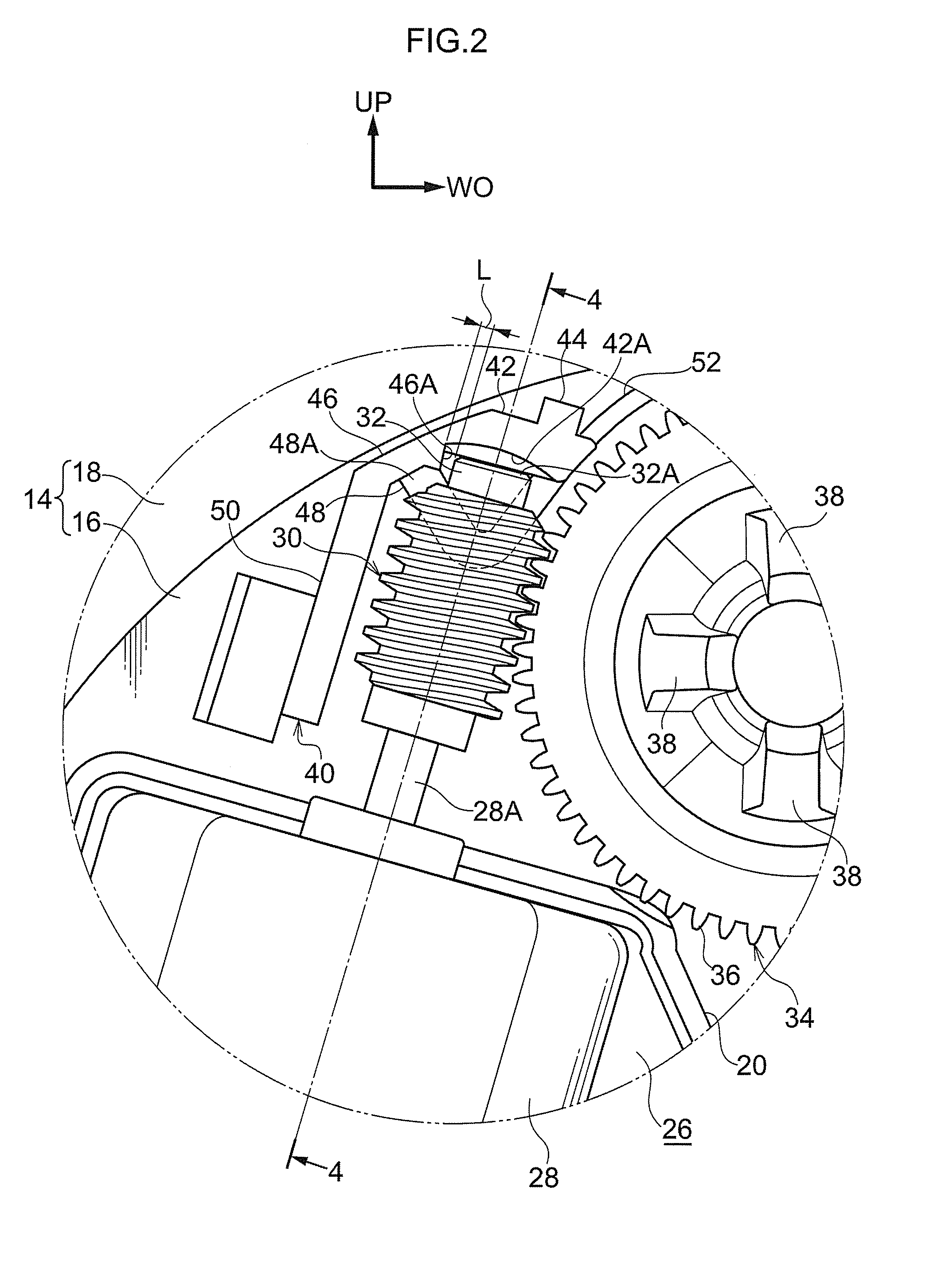
[0040]FIG. 7 is a front view of main portions of a vehicle door mirror apparatus 10 in which a vehicle mirror apparatus of the present invention is applied, as viewed from a vehicle rear direction. FIG. 8 is a cross-section (a cross-section taken on line 8-8 of FIG. 7) as viewed from the vehicle width direction outside (vehicle right hand side) of main portions of the vehicle door mirror apparatus 10. In the drawings arrow FR indicates the vehicle front direction, arrow WO indicates the vehicle width direction outside, and arrow UP indicates the upward direction.

[0041]The vehicle door mirror apparatus 10 according to the present exemplary embodiment is mounted to a vehicle door, with a mirror-face adjustment device 12 (mirror-face angle adjustment device) illustrated in FIG. 7 and FIG. 8 internally provided to the vehicle door mirror apparatus 10.

[0042]As shown in FIG. 1 and FIG. 5, the mirror-face adjustment device 12 is provided with a case 14 that serves as a mounting member and ...


PUM


Abstract

There is provided a vehicle mirror apparatus including: a mirror provided to a vehicle; a worm gear rotated by driving force from a base end side of the worm gear; a wheel gear engaged with the worm gear, the wheel gear adjusting a mirror-face angle of the mirror by being rotated due to the worm gear rotating; and a radial direction stopper portion that stops radial direction displacement of the worm gear towards the wheel gear radial direction outside by the leading end side of the worm gear making contact with the radial direction stopper portion.

Description

CROSS-REFERENCE TO RELATED APPLICATION[0001]This application claims priority under 35 USC 119 from Japanese Patent Application No. 2010-267554 filed Nov. 30, 2010, the disclosure of which is incorporated by reference herein.BACKGROUND[0002]1. Technical Field[0003]The present invention is related to a vehicle mirror apparatus in which the mirror-face angle of a mirror is adjusted by a worm gear being rotated to rotate a wheel gear.[0004]2. Related Art[0005]In a mirror-face adjusting actuator described in Japanese Patent Application Laid-Open (JP-A) No. 2006-88788, a worm gear is connected to the rotation shaft of a motor, the worm gear is meshed with a worm wheel, and the worm wheel is rotated by rotating the worm gear using motor driving force, thereby tilting a side mirror. The mirror-face angle of the side mirror is accordingly adjusted.[0006]However, with the mirror-face adjusting actuator, and in particular in circumstances in which tilting of the side mirror is stopped and rota...

Claims


Application Information

Patent Timeline
IPC IPC(8): B60R1/06
CPCB60R1/072
Inventor SUMI, ISAOKUDO, NOBUHIRO
Owner KK TOKAI RIKA DENKI SEISAKUSHO
Why Eureka
Try Eureka