Liquid separation apparatus for removing a liquid from a respiratory gas and respiratory gas analyzing system

Inactive Publication Date: 2012-05-31
WECKSTROM KURT PETER
View PDF5 Cites 15 Cited by
  • Summary
  • Abstract
  • Description
  • Claims
  • Application Information

AI Technical Summary

Benefits of technology

[0008]The above-mentioned shortcomings, disadvantages and problems are addressed herein which will be understood by reading and understanding the following specification.
[0009]In an embodiment, a liquid separation apparatus for removing a liquid from a respiratory gas is provided. The liquid separation apparatus comprises a housing that comprises an input, wherein a sample withdrawn from the respiratory gas is delivered through the input; a first output wherein at least part of the sample of the respiratory gas is discharged through the first output; and a first filter configured to remove the liquid from the sample of respiratory gas flowing through the input and the first output of the housing. The first filter comprises a hydrophobic property and an oleophobic property to remove the liquid when a surface tension of the liquid is lower than a surface tension of bodily fluids.
[0010]In another embodiment, a respiratory gas analyzing system is provided. The respiratory gas analyzing system comprises a gas analyzer configured to analyze respiratory gases, wherein the gas analyzer comprises a gas sensor configured to measure at least one gas component, and a gas withdrawing apparatus configured to withdraw the respiratory gases from the gas sensor. The respiratory gas analyzing system further comprises a liquid separation apparatus arranged upstream of the gas sensor, the liquid separation apparatus comprising a housing that comprises an input, wherein a sample withdrawn from the respiratory gas is delivered through the input; a first output wherein at least part of the sample of the respiratory gas is discharged through the first output; and a first filter configured to remove the liquid from the sample of respiratory gas flowing through the input and the first output of the housing. The first filter comprises a hydrophobic property and an oleophobic property to remove the liquid when a surface tension of the liquid is lower than a surface tension of bodily fluids.
[0009]In an embodiment, a liquid separation apparatus for removing a liquid from a respiratory gas is provided. The liquid separation apparatus comprises a housing that comprises an input, wherein a sample withdrawn from the respiratory gas is delivered through the input; a first output wherein at least part of the sample of the respiratory gas is discharged through the first output; and a first filter configured to remove the liquid from the sample of respiratory gas flowing through the input and the first output of the housing. The first filter comprises a hydrophobic property and an oleophobic property to remove the liquid when a surface tension of the liquid is lower than a surface tension of bodily fluids.

Problems solved by technology

Such components carried along with the sample would have a detrimental effect on the gas analyzer and measuring result.
It is possible that the device can handle a small amount of water but it is easily obstructed by mucus or blood.
This may happen quite often in critical care use and would decrease the cost-effectiveness of the device.
Still worse, a reduced surface tension of a nebulized liquid sucked into the hydrophobic filter could wet the filter and decrease its water entry pressure to a level where water freely would enter the analyzer together with the drug.
On the other hand, an adapter is inconvenient, and even risky for the patient, to remove from the respiratory circuit for the nebulization procedure.
As earlier mentioned, permeability problems may occur if the liquid has reduced surface tension like many drugs used for nebulization.
In practice, this is inconvenient and can easily be overlooked.
As a result the gas sensor and other internal parts of the gas analyzer may be contaminated.

Method used


Image

  • Liquid separation apparatus for removing a liquid from a respiratory gas and respiratory gas analyzing system
  • Liquid separation apparatus for removing a liquid from a respiratory gas and respiratory gas analyzing system
  • Liquid separation apparatus for removing a liquid from a respiratory gas and respiratory gas analyzing system

Examples


Embodiment Construction

[0019]Specific embodiments are explained in the following detailed description making a reference to accompanying drawings. These detailed embodiments can naturally be modified and should not limit the scope of the invention as set forth in the claims.

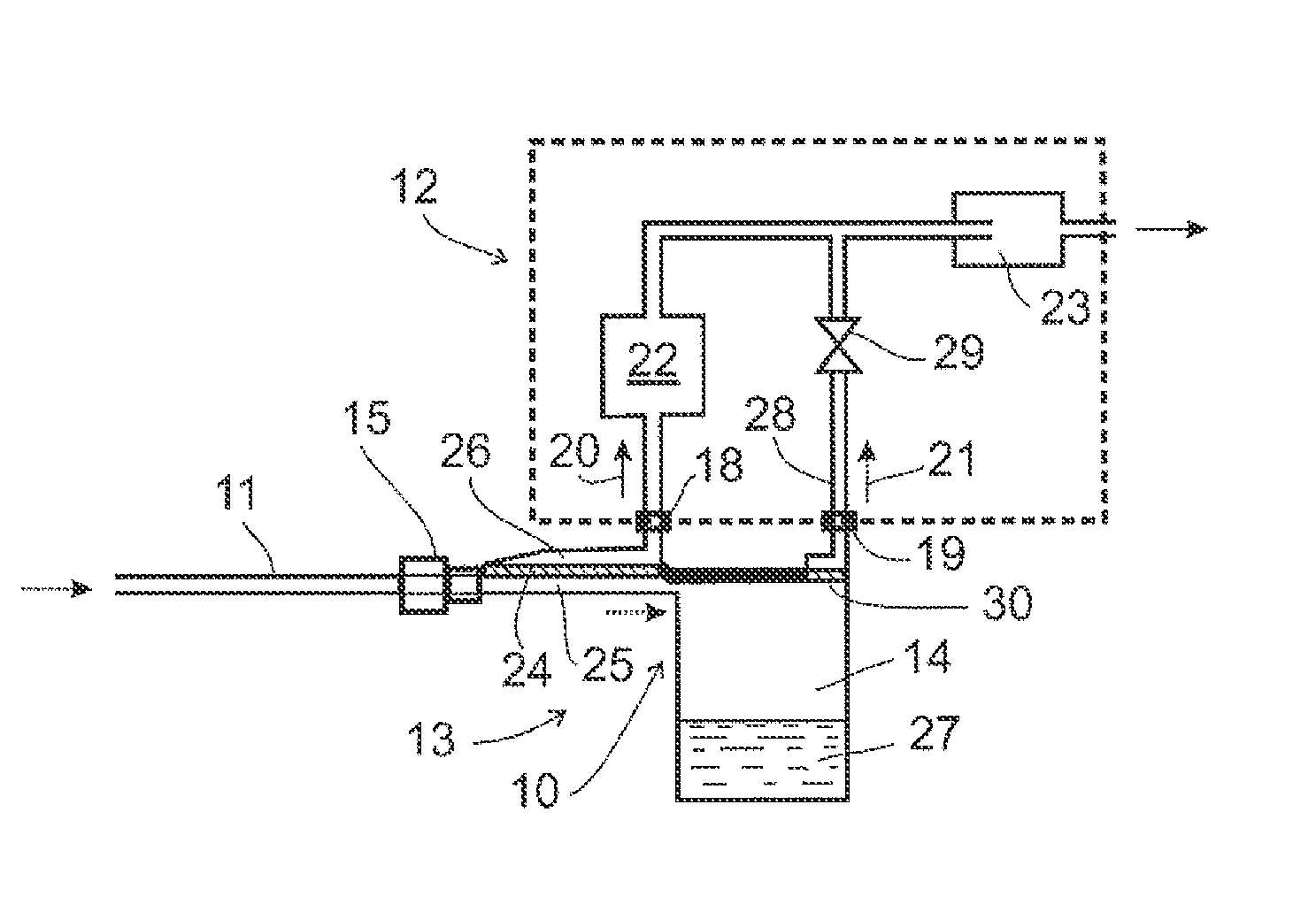
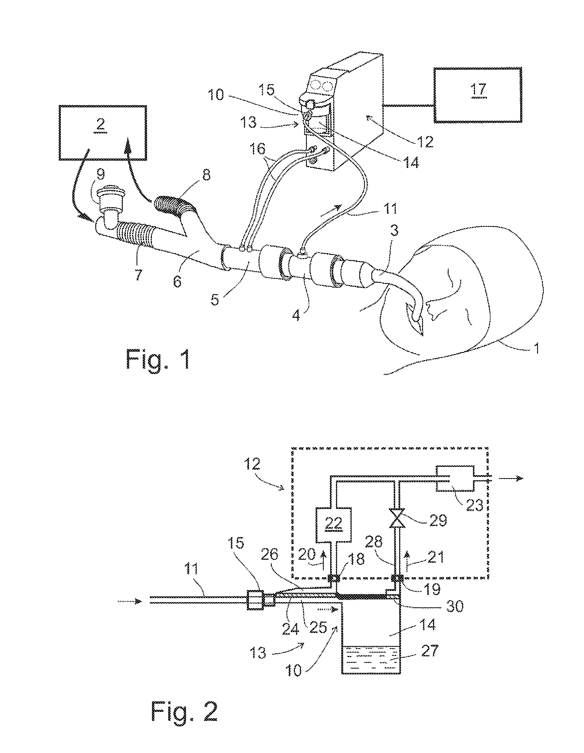
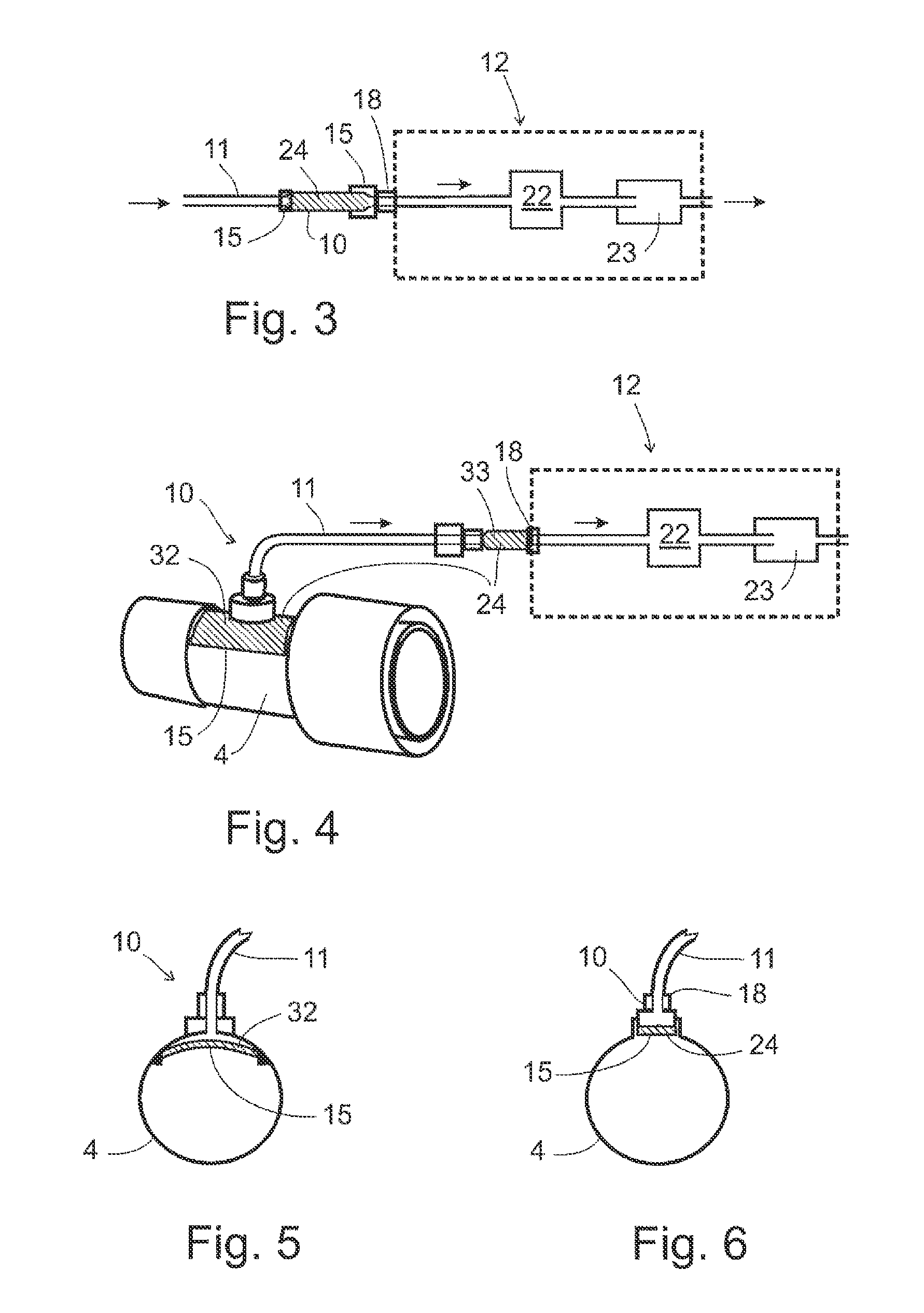
[0020]A liquid separation apparatus comprising hydrophobic filter upstream an analyzer analyzing gas samples withdrawn from a respiratory gas as described hereinbefore work to satisfaction in the majority of cases but it does not tolerate liquids with a reduced surface tension. Many drugs used in nebulizers include surfactants or the surface tension is reduced for other reasons. Also sputum and blood has a surface tension lower than that of water. The hydrophobic filter must then not only have high enough entry pressure for water but also for liquids with lower surface tension. Such filters are sometimes called superphobic or oleophobic because the surface tension of oil is smaller than that of water. Thus the filter material rejects o...


PUM

PropertyMeasurementUnit
Surface energyaaaaaaaaaa
Hydrophobicityaaaaaaaaaa

Abstract

A liquid separation apparatus for removing a liquid from a respiratory gas is provided. The liquid separation apparatus comprises a housing that comprises an input, wherein a sample withdrawn from the respiratory gas is delivered through the input; a first output wherein at least part of the sample of the respiratory gas is discharged through the first output; and a first filter configured to remove the liquid from the sample of respiratory gas flowing through the input and the first output of the housing. The first filter comprises a hydrophobic property and an oleophobic property to remove the liquid when a surface tension of the liquid is lower than a surface tension of bodily fluids.

Description

BACKGROUND OF THE INVENTION[0001]1. Field of the Invention[0002]This disclosure relates generally to a liquid separation apparatus for removing a liquid from a respiratory gas comprising a housing having an input for delivering a sample withdrawn from the respiratory gas, a first output for discharging at least part of the sample of the respiratory gas and a first filter with a hydrophobic property for removing the liquid from the gas sample flowing through the input and first output of the housing. Also this disclosure relates to a respiratory gas analyzing system.[0003]2. Description of Related Art[0004]In anesthesia or in intensive care, the condition of a patient is often monitored e.g. by analyzing the gas exhaled by the patient for its content. For this reason a small portion of the respiratory gas may be diverted to a gas analyzer. This sample often carries along to the analyzer some water vapor, which condensates into droplets, and also some dust, water, mucus and blood. Suc...

Claims


Application Information

Patent Timeline
IPC IPC(8): A61B5/08G01N33/497B01D46/00
CPCA61B5/083A61M16/0808A61M16/0816A61M2205/7536A61M2205/7563A61M2230/432A61M16/085A61M2230/437A61B5/082A61B5/0833A61B5/0836A61B5/097A61M2230/435A61M16/1055A61M16/0833A61M16/1065
Inventor WECKSTROM, KURT PETER
Owner WECKSTROM KURT PETER
Why Eureka
Try Eureka