Autoinjector

a technology of auto-injector and injection tube, which is applied in the direction of intravenous device, infusion needle, other medical devices, etc., can solve the problems of inability to deliver sufficiently quickly, unintuitive, complicated extra steps,

Active Publication Date: 2012-05-31
SHL MEDICAL AG
View PDF2 Cites 48 Cited by
  • Summary
  • Abstract
  • Description
  • Claims
  • Application Information

AI Technical Summary

Benefits of technology

The invention prevents an inner housing from moving forwards when it receives energy through a certain mechanism. This happens because there are blocks that stop the inner housing from moving in its own direction.

Problems solved by technology

The technical problem addressed in this patent is the potential danger of accidental delivery of medicament in autoinjector devices that use easy-to-operate actuation means, and the difficulty in quickly delivering a dose of medicament in emergency situations where the user may be panicked or suffering.

Method used


Image

  • Autoinjector
  • Autoinjector
  • Autoinjector

Examples


Embodiment Construction

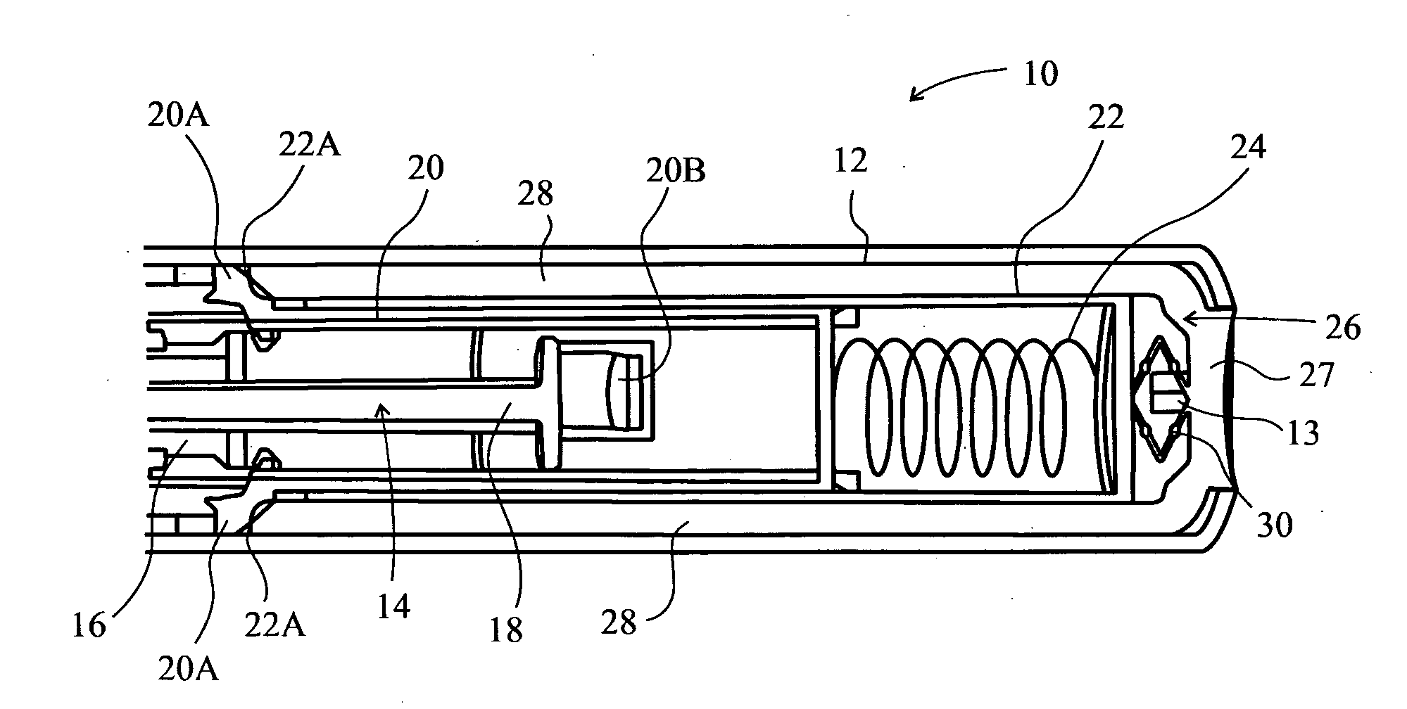
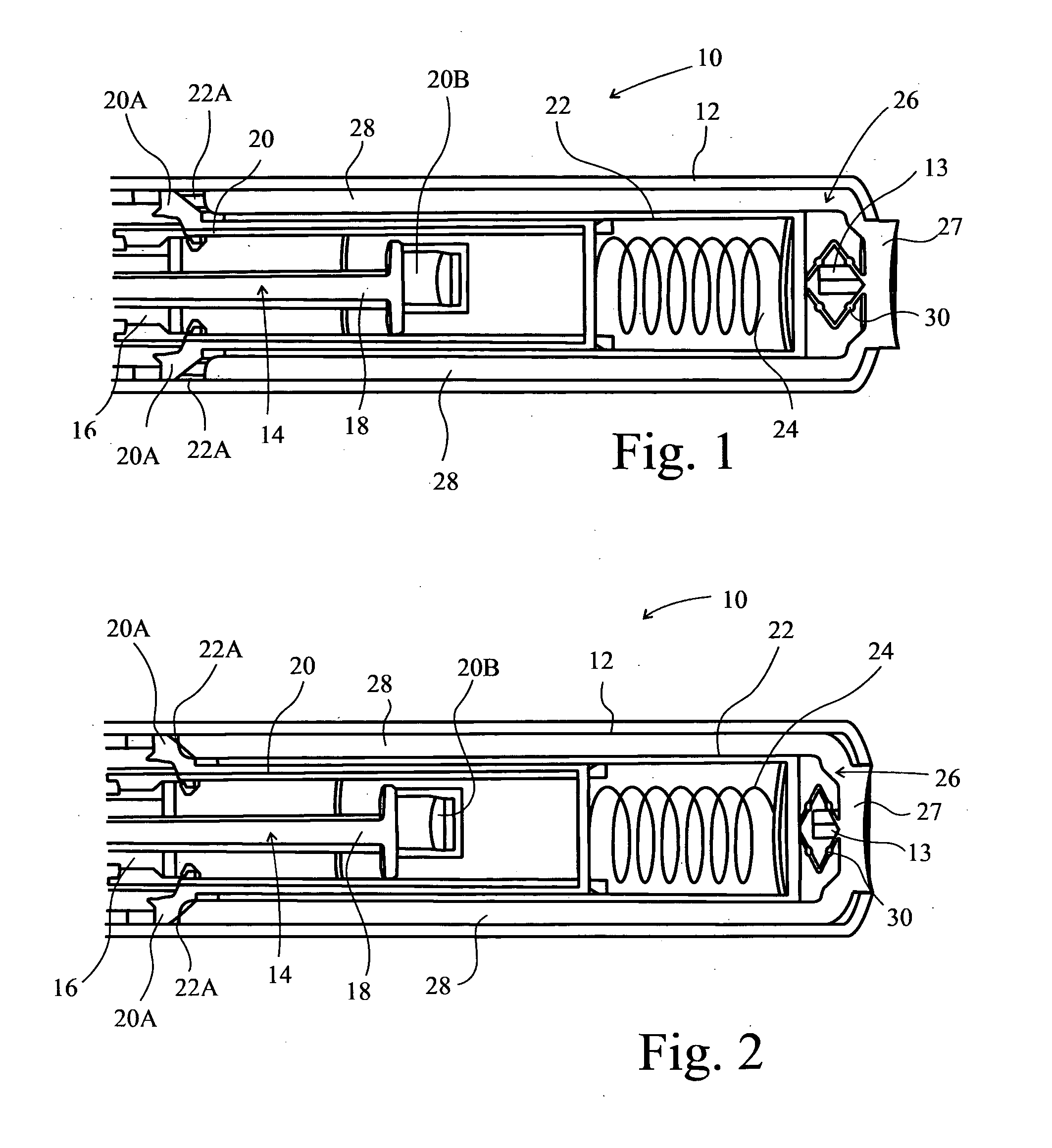
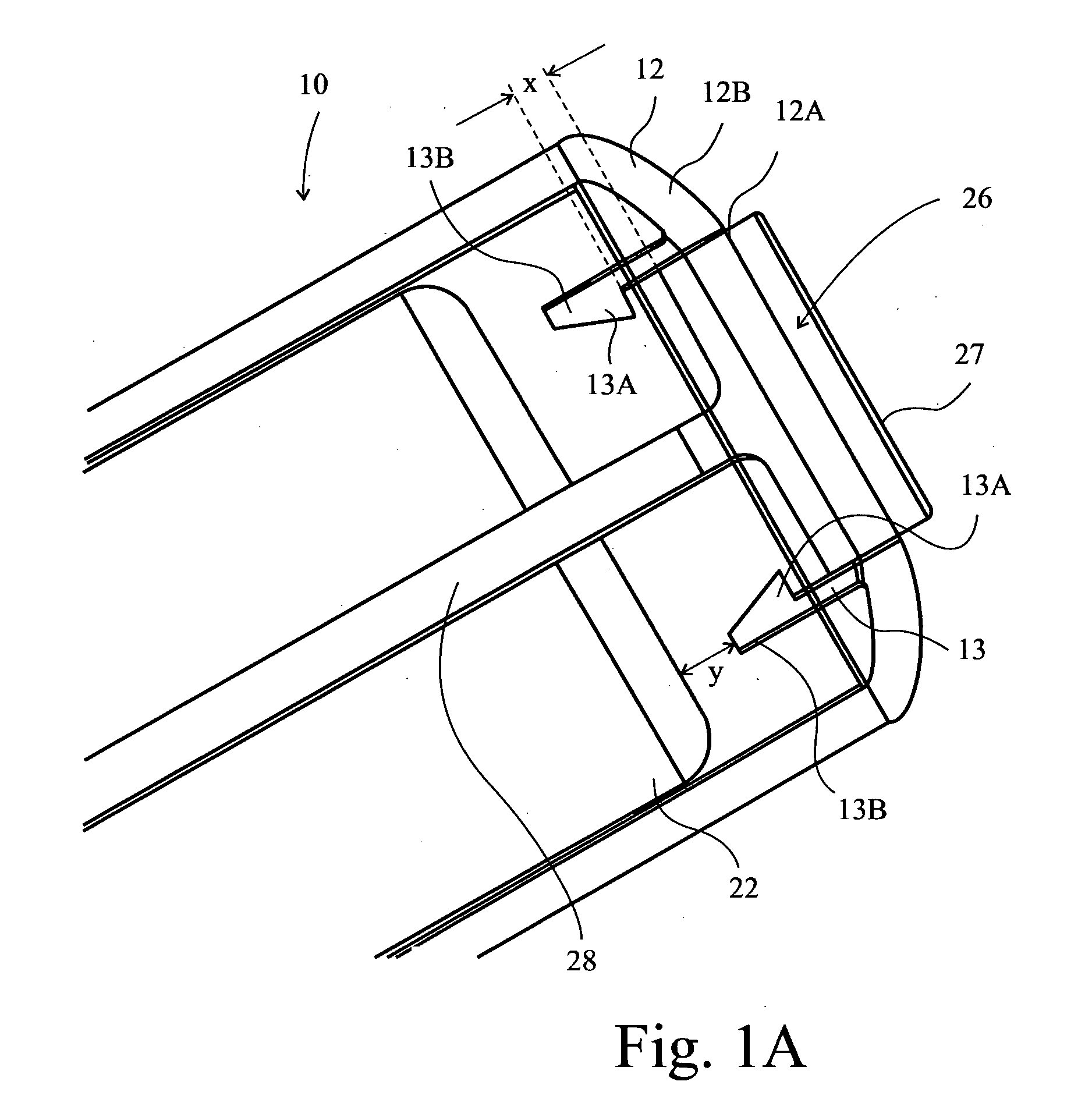
[0032]FIG. 1 shows a sectional view of an exemplary embodiment of an autoinjector device 10 according to present invention. The device 10 has a housing including an outer housing 12 which houses a syringe 14. The syringe 14 is adapted to hold a volume of medicament and comprises a barrel 16, a needle (not shown) at one end of the barrel 16, and a plunger 18, axially moveable within the barrel 16. The needle is axially moveable in and out of a front end of the device's housing but is biased to be normally wholly inside the housing.

[0033]The device further comprises an inner housing 20 disposed intermediate the outer housing 12 and at least part of the syringe 14. Prior to actuation for delivery of medicament, at least a part of the inner housing 20 is disposed axially rearward of the barrel 16 of the syringe 14. The device 10 further comprises a spring housing 22 intermediate a portion of the inner housing 20 and the outer housing 12. A spring 24 is located between the spring housing...


PUM


Abstract

An injection device comprising an outer housing adapted to receive a syringe for holding a volume of a medicament, said syringe comprising a barrel, a needle at one end of the barrel, and a plunger, axially moveable within the barrel, the needle and barrel being such that at least part of the needle is axially moveable in and out of said outer housing but is biased to be normally wholly inside said housing. The injection device further comprises an inner housing intermediate the outer housing and at least part of the barrel and/or plunger, an energy source in communication with the inner housing, and blocking means capable of preventing said inner housing moving axially under the influence of said energy source. The device is moveable between two positions, namely a first position in which the inner housing is prevented from moving axially forward by engagement with said blocking means; and a second position in which the inner housing is disengaged from said blocking means and is capable of acting on the syringe under the influence of said energy source to move said at least part of the needle out of said outer housing. The device is moveable from said first position to said second position by movement of said outer housing relative to said inner housing and actuation of a trigger.

Description


Claims


Application Information

Patent Timeline
Owner SHL MEDICAL AG
Why Eureka
Try Eureka