Eureka AIR delivers breakthrough ideas for toughest innovation challenges, trusted by R&D personnel around the world.

Folding rifle stock

a rifle stock and stock clip technology, applied in the field of rifles, can solve the problems of affecting accuracy, affecting the stability of the folding mechanism, and being considered undesirable for military us

Inactive Publication Date: 2012-06-07
H S PRECISION
View PDF5 Cites 37 Cited by
  • Summary
  • Abstract
  • Description
  • Claims
  • Application Information

AI Technical Summary

Benefits of technology

"The present invention provides a folding rifle stock that overcomes the limitations of existing folding stocks. The stock has a forward portion for securing to a rifle action and a rear portion with a shoulder-engagement surface. The forward portion and rear portion are pivotally connected and movable between an extended position and a folded position. The rear portion includes a grip positioned adjacent to a trigger location on the front portion, so that a finger on a user's hand gripping the grip may operate the trigger when the stock is in the extended position. The hinge is adjustable to take up slack due to wear, with a tapered hinge pin, and one hinge portion configured to selectable clamp a threaded portion of the hinge pin. The hinge includes a latch to lock the stock in the extended position, and the lock may include a wedging cam element to generate torque to bias the stock to the extended position."

Problems solved by technology

Flexure of a stock can apply stresses and pressure to the action or barrel, impairing accuracy.
This might be considered undesirable for military use where a stock is folded in close quarters, or when a stowed rifle needs to be rapidly brought into action, such as by a paratrooper who jumps with a folded stock for safety reasons.
A further disadvantage of existing folding stocks is that the folding mechanism is subject to loosening from wear, or otherwise introduces flexibility or movement that can impair accuracy.
In some environments, debris can impair operation of the mechanism as well.

Method used


Image

  • Folding rifle stock
  • Folding rifle stock
  • Folding rifle stock

Examples


Embodiment Construction

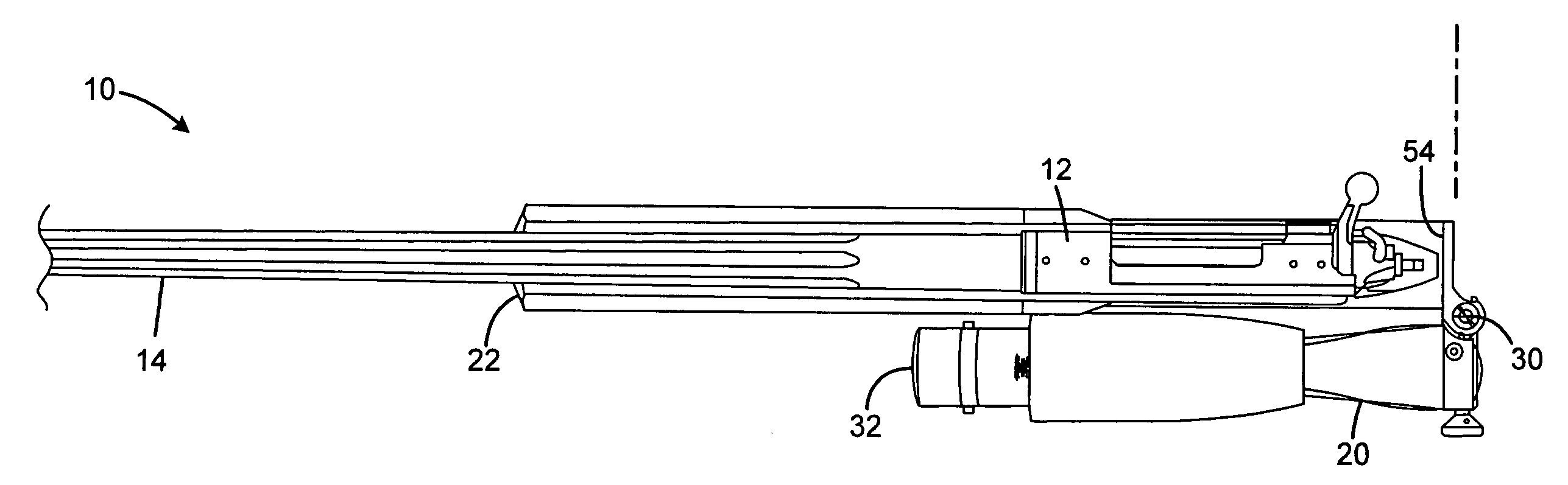
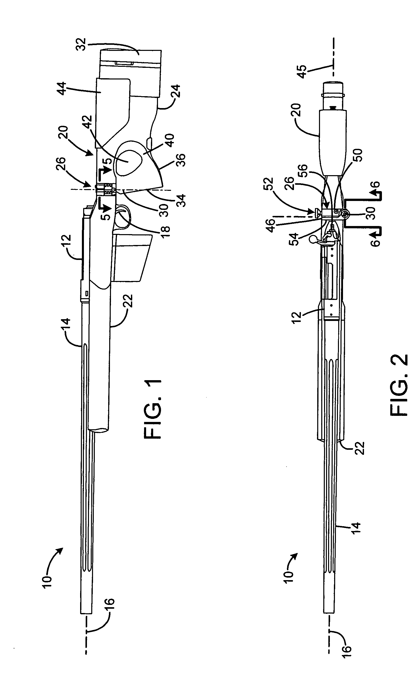
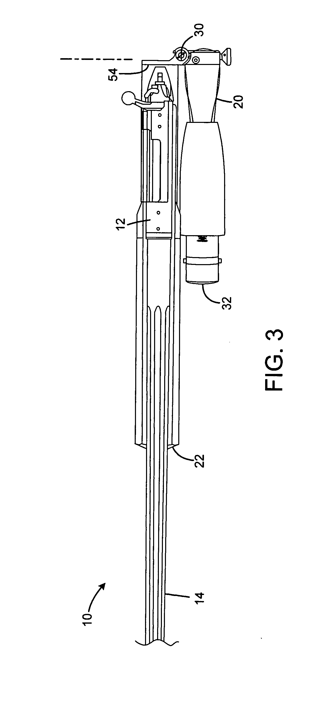
[0014]FIG. 1 shows a rifle 10 having an action 12 with an extending barrel 14 defining a bore axis 16. A trigger 18 extends downward from the action near the rear. While shown as a conventional bolt action rifle, alternative embodiments may include any other type of conventional or novel firearm action.

[0015]A folding stock 20 according to the present invention has a forward portion 22 secured to the action 12, and extending below a portion of the barrel. A rear stock portion 24 is connected to the forward portion by a hinge assembly 26 defining a vertical pivot axis 30. The rear portion has a butt pad surface 32 at the rear for engaging a user's shoulder for aiming and firing the rifle.

[0016]The rear portion has a grip 34 near the hinge at the forward portion of the rear portion of the stock. The grip extends downward and slightly rearward from the hinge, at an angle common to pistol grips. The grip is intended for grasping by the user's dominant hand that will be used to pull the ...


PUM


Abstract

A folding rifle stock has a forward portion for securing to a rifle action having a barrel and trigger. The stock has a rear portion having a shoulder-engagement surface. The forward portion and rear portion are pivotally connected and movable between an extended position and a folded position. The rear portion includes a grip positioned adjacent to a trigger location on the front portion, so that a finger on a user's hand gripping the grip may operate the trigger when the stock is in the extended position. The hinge may be directly connected to a metal bedding block in the front portion. The hinge may be adjustable to take up slack due to wear, with a tapered hinge pin, and with one hinge portion configured to selectable clamp a threaded portion of the hinge pin. The hinge may include a latch to lock the stock in the extended position, and the lock may include a wedging cam element to generate torque to bias the stock to the extended position.

Description

FIELD OF THE INVENTION[0001]This invention relates to the firearms, and more particularly to hinged or folding stocks for rifles.BACKGROUND AND SUMMARY OF THE INVENTION[0002]Conventional rifles such as bolt-action rifles have stocks that provide a comfortable, ergonomic shoulder rest and gripping surfaces. The stock receives the operating parts of the rifle, which are assembled as a barreled action that is securely attached to and partially enveloped by the stock. Normally stocks are in one piece, to provide rigidity. Flexure of a stock can apply stresses and pressure to the action or barrel, impairing accuracy.[0003]Folding stocks are employed to make a rifle more compact for storage, transport, and for use in close quarters where a full length stocked rifle would be unwieldy. Such stocks are well known on military rifles, which normally have a protruding pistol grip. Other folding stock rifles have thumbhole stocks that have a handgrip for the trigger hand, but which is connected ...

Claims


Application Information

Patent Timeline
Patent Type & Authority Applications(United States)
IPC IPC(8): F41C23/04
CPCF41C23/04
Inventor LUDLOW, CHRISTOPHER ALLEN
Owner H S PRECISION
Why Eureka
Eureka Blog
Learn More