Method for connecting components of a microfluidic flow cell

Active Publication Date: 2019-07-09
THINXXS MICROTECHNOLOGY AG
View PDF5 Cites 0 Cited by
  • Summary
  • Abstract
  • Description
  • Claims
  • Application Information

AI Technical Summary

Benefits of technology

[0007]The invention is based on the goal of creating a new method of the type described above which makes it possible to connect components of a flow cell with increased precision and manufacturing reliability.
[0011]material of at least one of the components bordering the gap dissolves in the solvent;
[0012]after the solvent has evaporated, this material fills up the entire width and a portion of the height of the gap, thus connecting the components to each other.
[0013]It is advantageous that, because of its good wetting properties, a solvent of this type can quickly penetrate into very narrow assembly gaps by capillary action, which makes it possible to achieve high precision with respect to the mutual positioning of the components to be connected to each other.
[0014]To fill relatively large gaps, the solvent t

Problems solved by technology

Flow cells of this type are undergoing a process of progressive miniaturization and increasing functional complexity, with the result that such flow cells are now being called “labs on a chip”.
Especially in the production of complex flow cells, the cost of materials can be very high.
The aspect ratios realizable by this latter method, however are much lower than in the methods of semiconductor technology, which is a disadvantage.
The disadvantage here is that there is now a third material present, i.e., not only the plastic material of the carrier structure and the material of the microcomponent integrated into it but also the adhesive material, which can then come into direct contact with the fluids to be tested.
This can result in faulty measurements.
Nor is it possible to exclude the possibility of toxic effects on the biological sample material.
Anoth

Method used


Image

  • Method for connecting components of a microfluidic flow cell
  • Method for connecting components of a microfluidic flow cell
  • Method for connecting components of a microfluidic flow cell

Examples


Embodiment Construction

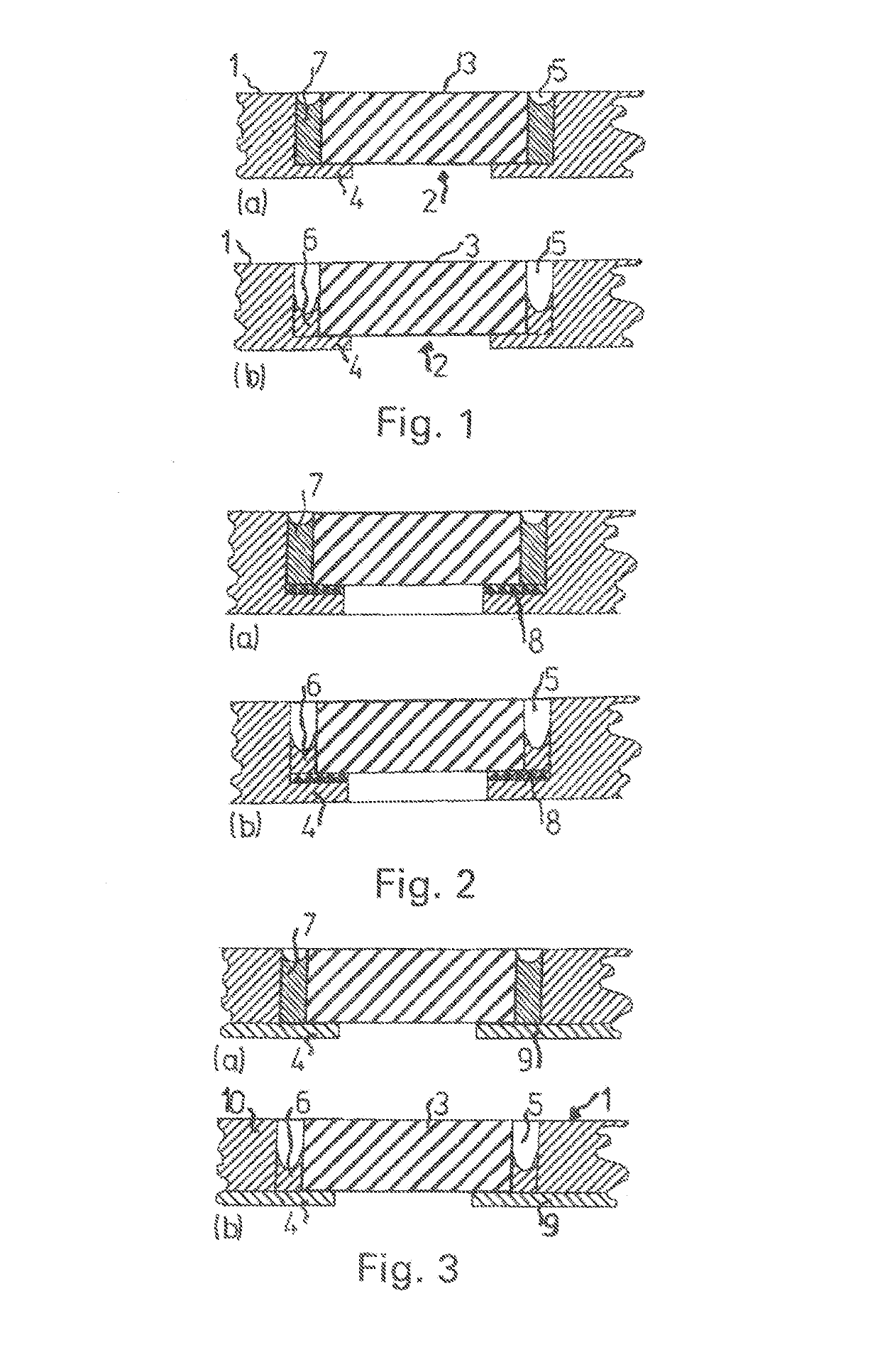
[0033]A microfluidic flow cell as shown partially in FIG. 1 comprises a plate-shaped carrier structure 1, which consists preferably of an amorphous plastic such as PMMA, PC, PS, COC, or COP.

[0034]A microcomponent 3—in the example shown, a component with the basic form of a circular disk or a square plate—is arranged in a pocket 2 of the carrier structure 1. The microcomponent is preferably made of silicon, but it can also be formed out of metal, ceramic, plastic, or glass with a surface which can be functionalized in various ways.

[0035]The microcomponent 3 rests on a ring-shaped shoulder 4 of the pocket 2; except for this shoulder, the pocket passes straight through the entire thickness of the carrier structure 1. An annular gap 5, formed between the carrier structure 1 and the microcomponent 3, is open on one axial side, whereas, on the other axial side, it is closed off by the ring-shaped shoulder 4 of the carrier structure 1. The width 3 of the annular gap 5 is typically in the r...


PUM

PropertyMeasurementUnit
Temperatureaaaaaaaaaa
Thicknessaaaaaaaaaa
Forceaaaaaaaaaa

Abstract

A flow cell and a method for connecting components of a microfluidic flow cell, in particular for integrating component parts into a carrier structure of the flow cell, in which a gap is formed between the components to be connected. The gap is filled with a solvent. The material of at least one component bordering the gap dissolves in the solvent and the material completely fills the width of the gap and partially fills the height thereof after evaporation of the solvent.

Description

[0001]The present application is a 371 of International application PCT / DE2013 / 100408, filed Dec. 5, 2013, which claims priority of DE 10 2012 112 306.3, filed Dec. 14, 2012, the priority of these applications is hereby claimed and these applications are incorporated herein by reference.BACKGROUND OF THE INVENTION[0002]The invention pertains to a method for connecting components of a microfluidic flow cell, especially for integrating microcomponents into a carrier structure of the flow cell. The invention also pertains to a flow cell produced by the method.[0003]The primary area of application for the method under consideration is the production of flow cells such as those used, for example, in medical analysis and diagnostics, in biochemistry, and in molecular biology as well as in drug development; these flow cells comprise a carrier structure of plastic, into which functional components, especially sensors of silicon, glass, or metal, are integrated. Flow cells of this type are u...

Claims


Application Information

Patent Timeline
IPC IPC(8): B01L3/00B29C65/00B29C65/48B29C65/54B29L22/00B29L31/00
CPCB01L3/502707B29C65/4895B29C65/54B29C66/1222B29C66/1224B29C66/47B29C66/5346B29C66/61B29C66/73771B29L2031/756B29L2022/00B29C66/7392B29C66/71B01L2300/12B01L2300/0877B01L2300/0816B01L2200/027B01L2200/0689B01L2200/12B01L2300/0636B01L2300/0645B29K2033/12B29K2069/00B29K2025/06B29K2023/38
Inventor WEBER, LUTZ
Owner THINXXS MICROTECHNOLOGY AG
Why Eureka
Try Eureka