Eureka AIR delivers breakthrough ideas for toughest innovation challenges, trusted by R&D personnel around the world.

Method for connecting components of a microfluidic flow cell

a microfluidic flow cell and component technology, applied in the field of connecting components of microfluidic flow cells, can solve the problems high cost of materials, and achieve the effects of increasing functional complexity, low cost, and high cost of materials

Active Publication Date: 2022-09-27
THINXXS MICROTECHNOLOGY AG
View PDF8 Cites 0 Cited by
  • Summary
  • Abstract
  • Description
  • Claims
  • Application Information

AI Technical Summary

Benefits of technology

The patent text describes a method for connecting components of a microfluidic flow cell, especially for integrating microcomponents into a carrier structure of the flow cell. The method aims to overcome the disadvantages of existing methods such as the use of adhesive materials that have low wettability, require wide gaps, and can destroy functional components. The technical effects of the method include improved accuracy in positioning microcomponents, reduced measurement faults, and reduced toxic effects on biological samples. The method can be used in the production of miniaturized flow cells for medical diagnosis and drug development.

Problems solved by technology

Flow cells of this type are undergoing a process of progressive miniaturization and increasing functional complexity, with the result that such flow cells are now being called “labs on a chip”.
Especially in the production of complex flow cells, the cost of materials can be very high.
The aspect ratios realizable by this latter method, however are much lower than in the methods of semiconductor technology, which is a disadvantage.

Method used


Image

  • Method for connecting components of a microfluidic flow cell
  • Method for connecting components of a microfluidic flow cell
  • Method for connecting components of a microfluidic flow cell

Examples


Embodiment Construction

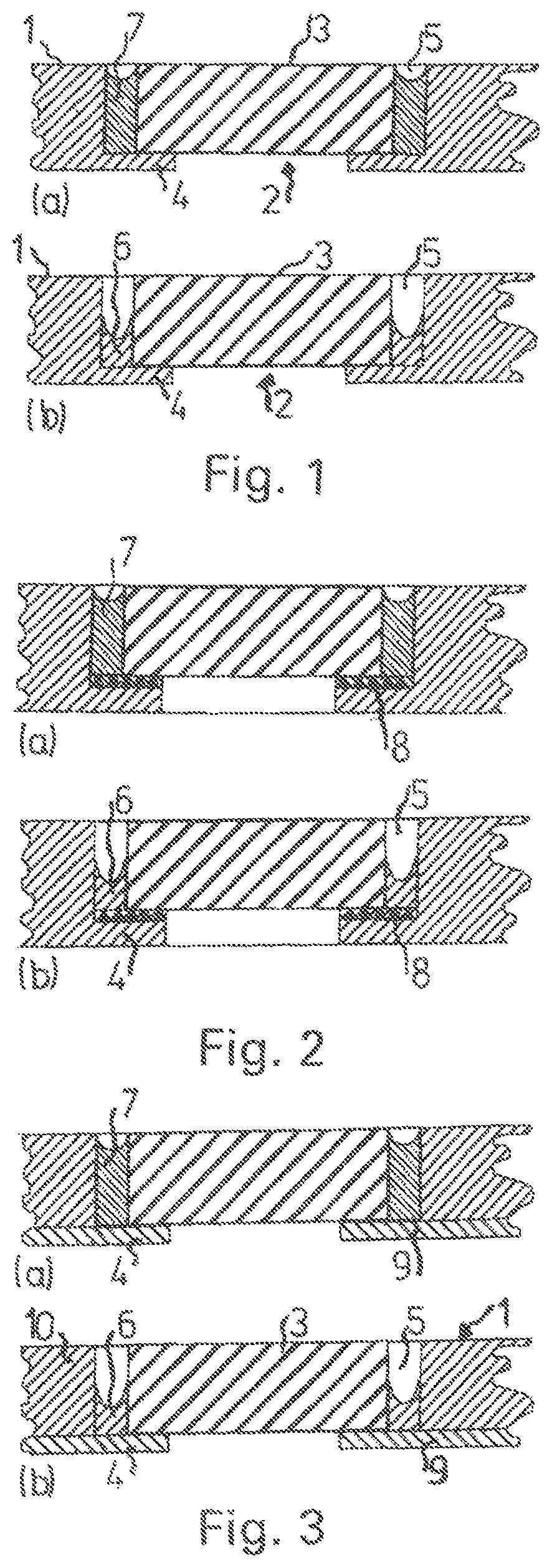
[0038]A microfluidic flow cell as shown partially in FIG. 1 comprises a plate-shaped carrier structure 1, which consists preferably of an amorphous plastic such as PMMA, PC, PS, COC, or COP.

[0039]A microcomponent 3—in the example shown, a component with the basic form of a circular disk or a square plate—is arranged in a pocket 2 of the carrier structure 1. The microcomponent is preferably made of silicon, but it can also be formed out of metal, ceramic, plastic, or glass with a surface which can be functionalized in various ways.

[0040]The microcomponent 3 rests on a ring-shaped shoulder 4 of the pocket 2; except for this shoulder, the pocket passes straight through the entire thickness of the carrier structure 1. An annular gap 5, formed between the carrier structure 1 and the microcomponent 3, is open on one axial side, whereas, on the other axial side, it is closed off by the ring-shaped shoulder 4 of the carrier structure 1. The width 3 of the annular gap 5 is typically in the r...


PUM


Abstract

A flow cell and a method for connecting components of a microfluidic flow cell, in particular for integrating component parts into a carrier structure of the flow cell, in which a gap is formed between the components to be connected. The gap is filled with a solvent. The material of at least one component bordering the gap dissolves in the solvent and the material completely fills the width of the gap and partially fills the height thereof after evaporation of the solvent.

Description

CROSS-REFERENCE TO RELATED APPLICATIONS[0001]The present application is a Divisional Application of U.S. patent application Ser. No. 14 / 652,316, filed Jun. 15, 2015, which is a 371 of International Application PCT / DE2013 / 100408 filed on Dec. 5, 2013 which claims the benefit of priority from German Patent Application No. 10 2012 112 306.3 filed Dec. 14, 2012, the contents of each of which are incorporated herein by reference.BACKGROUND OF THE INVENTION[0002]The invention pertains to a method for connecting components of a microfluidic flow cell, especially for integrating microcomponents into a carrier structure of the flow cell. The invention also pertains to a flow cell produced by the method.[0003]The primary area of application for the method under consideration is the production of flow cells such as those used, for example, in medical analysis and diagnostics, in biochemistry, and in molecular biology as well as in drug development; these flow cells comprise a carrier structure...

Claims


Application Information

Patent Timeline
Patent Type & Authority Patents(United States)
IPC IPC(8): B01L3/00B29C65/00B29C65/48B29C65/54B29L31/00B29L22/00
CPCB01L3/502707B29C65/4895B29C65/54B29C66/1222B29C66/1224B29C66/47B29C66/5346B29C66/61B29C66/73771B01L2200/027B01L2200/0689B01L2200/12B01L2300/0636B01L2300/0645B01L2300/0816B01L2300/0877B01L2300/12B29C66/71B29C66/7392B29L2022/00B29L2031/756B29K2033/12B29K2069/00B29K2025/06B29K2023/38
Inventor WEBER, LUTZ
Owner THINXXS MICROTECHNOLOGY AG
Why Eureka
Eureka Blog
Learn More