Wall conforming suspended ceiling molding

a ceiling molding and wall technology, applied in the direction of walls, constructions, building components, etc., can solve the problems of unsightly gaps between the wall angle and the wall, irregularities can be especially pronounced, and the wall is often not flat,

Inactive Publication Date: 2012-06-07
USG INTERIORS INC
View PDF25 Cites 13 Cited by
  • Summary
  • Abstract
  • Description
  • Claims
  • Application Information

AI Technical Summary

Benefits of technology

[0003]The invention provides a wall molding for suspended ceiling systems that is capable of conforming to ordinary deviations from a flat plane in the surface of a wall against which it is mounted. The inventive wall angle, in various embodiments, has a visible wall engaging area that, in a free state, projects from an upright component of the molding toward the wall. When the upright component of the molding is drawn against the wall surface, the visible wall engaging area retracts towards a plane of the upright component. Where the upright component is not locally drawn against or close to the wall surface because adjacent wall areas bulge or recede from a flat plane, the retractable visible wall engaging area remains extended towards the wall. Consequently, unsightly gaps between the visible wall engaging area of the molding and the wall are avoided. Advantageously, the molding can be roll-formed of a single metal strip sufficiently hard or springy to allow the strip to resiliently flex and allow retraction of the visible wall engaging area or, if adjustment is needed, allow return of this area to its free state. In a first disclosed embodiment, a metal strip forming the molding body is folded in a manner such that the visible wall engaging area is formed along an edge of the strip that is opposite the edge on a side of the strip that projects to support ceiling panel edges and grid runner ends. When the upright component is drawn towards a wall during installation of the molding, the visible wall engaging area telescopes or slides under adjacent areas of the projecting component.

Problems solved by technology

Walls conventionally constructed of drywall are often not flat because of the presence of corner bead, taped joints, and other disturbances.
These irregularities can be especially pronounced where a space is being remodeled and walls are reconfigured.
As a result, ordinary wall angle often does not closely follow the irregularities in a wall and unsightly gaps between the wall angle and the wall can exist.
While it is customary to conceal such gaps with caulk, this technique is undesirable as a solution to the problem of unsightly gaps.
Efforts to force the wall angle into full contact with an irregular wall surface can cause the wall angle to permanently buckle and present an even more unsightly condition.

Method used


Image

  • Wall conforming suspended ceiling molding
  • Wall conforming suspended ceiling molding
  • Wall conforming suspended ceiling molding

Examples


first embodiment

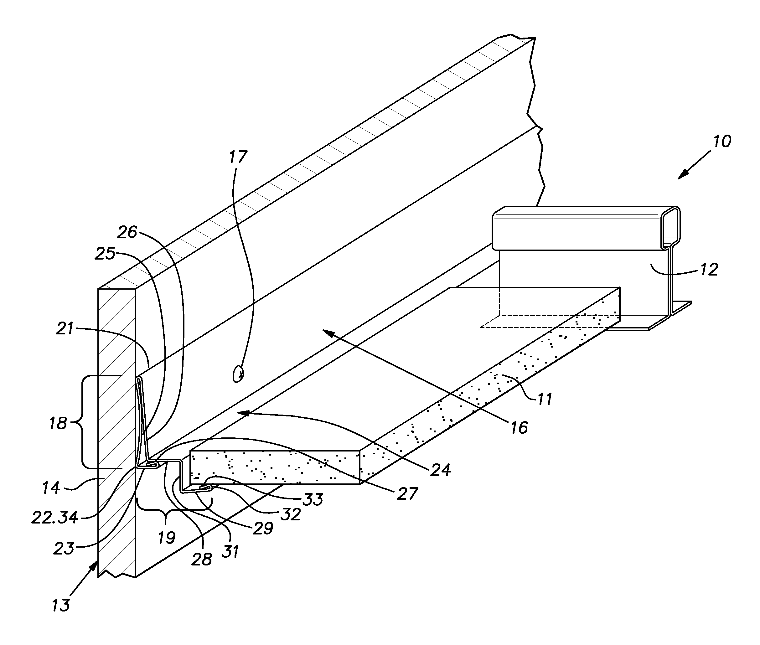
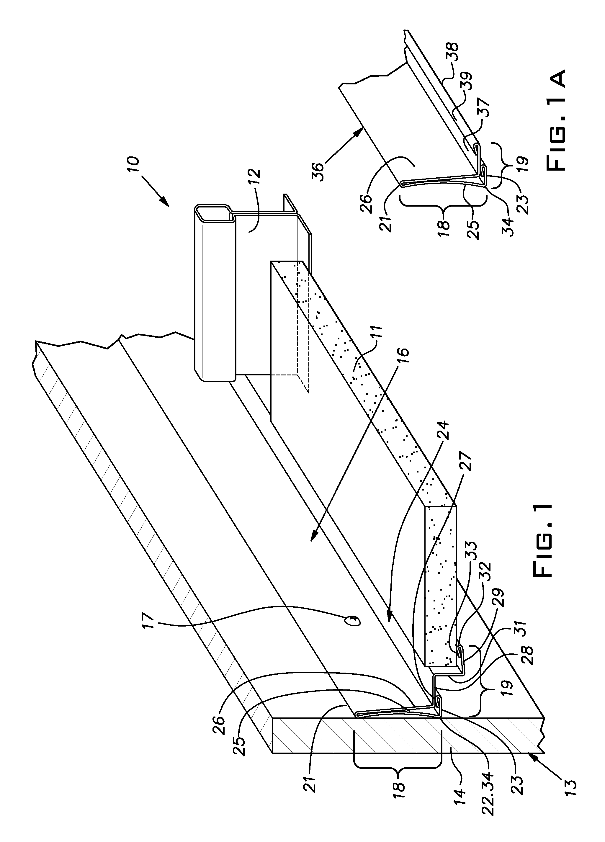
[0010]Where drywall sheets 14 are joined, particularly where their ends are abutted and taped or where they intersect at an outside corner and are capped with a corner bead and joint compound, the wall will have localized bulges meaning that the wall surface deviates from a flat plane. a wall molding 16 constructed in accordance with the invention is illustrated in FIG. 1. The molding 16 is secured to the wall 13 by fasteners 17 such as screws, nails, or staples. It is customary that the fasteners are driven through the drywall 14 into the underlying studs or other framework or support. Typically, the studs will be spaced horizontally a regular distance along the wall 13.

[0011]The wall molding 16 comprises a generally upright component 18 and a projecting component 19. The wall molding 16, preferably, is a single sheet of metal, typically steel sufficiently hard to exhibit a springiness or resilience as discussed below. The wall molding 16 while it can be brake-formed, is preferably...

second embodiment

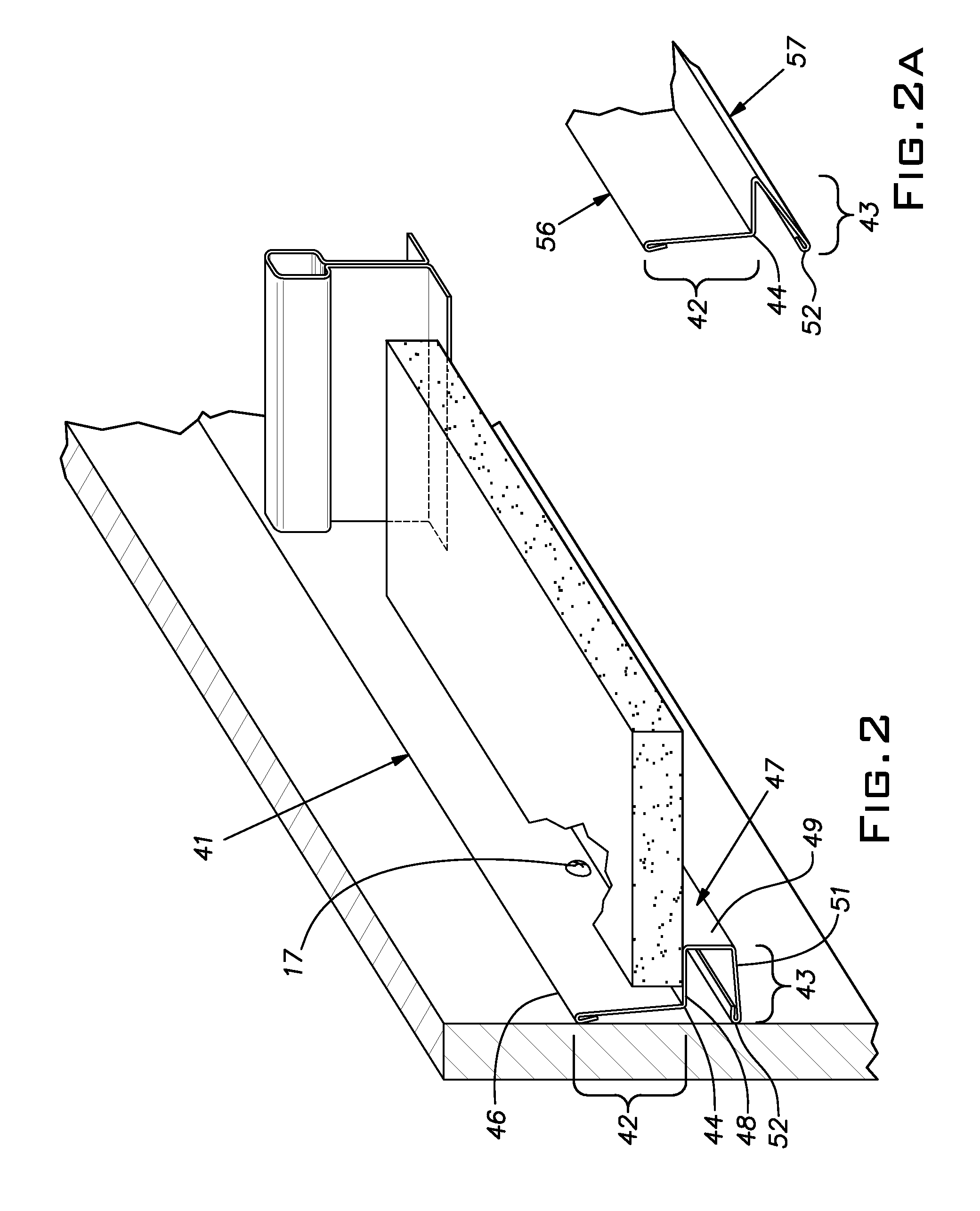
[0017]Referring now to FIG. 2, there is shown a wall molding 41. Identical or similar elements to that described in connection with FIG. 1 are identified with the same numerals in FIG. 2. The wall molding 41 as in the previous wall moldings 16, 36 is preferably roll-formed of half hard sheet steel of light gauge. The free state cross section of the wall molding 41 is illustrated in the foreground of FIG. 2 and is continuous along its length which, again, can be in the order of 10′ or 12′ or metric equivalent. The wall molding has an upright component 42 and a projecting component 43. The upright component 42 is generally planar extending upwards from a corner 44 it shares with the projecting component to an upper hemmed edge 46.

[0018]The projecting component 43 comprises a C-shaped channel 47 comprising an upper horizontal segment 48, a generally vertical segment 49, and a lower generally horizontal segment 51.

[0019]The lower segment 51 is somewhat longer than the upper horizontal s...


PUM


Abstract

A wall molding for a suspended ceiling comprising a roll-formed sheet metal body having a generally upright component to be fixed to a wall and a projecting component extending generally transversely to the upright component and adapted to underlie and support the edges of ceiling tiles and ends of grid runners, the projecting component in a free state extending across a plane defined by the upright component to a line adapted to abut the wall when the upright component is drawn towards the wall.

Description

BACKGROUND OF THE INVENTION[0001]The invention relates to suspended ceiling systems and, in particular, to an improved wall molding for use in such systems.PRIOR ART[0002]Where a suspended ceiling meets a wall, it is customary to provide a sheet metal wall angle. This wall angle serves to support the edges of ceiling panels or tiles and the ends of grid runners and to conceal normal gaps between these edges and ends and the wall. Walls conventionally constructed of drywall are often not flat because of the presence of corner bead, taped joints, and other disturbances. These irregularities can be especially pronounced where a space is being remodeled and walls are reconfigured. Standard metal wall angles, while ordinarily made of light gauge steel, are relatively stiff owing to the right angle geometry. As a result, ordinary wall angle often does not closely follow the irregularities in a wall and unsightly gaps between the wall angle and the wall can exist. While it is customary to ...

Claims


Application Information

Patent Timeline
Patent Type & Authority Applications(United States)
IPC IPC(8): E04B9/18
CPCE04B9/30
Inventor WENDT, ALAN C.
Owner USG INTERIORS INC
Why Eureka
Try Eureka