Retrofit system for doors, windows and framed openings

a technology for retrofitting and molding systems, applied in the field of molding systems, can solve the problems of labor-intensive filling of holes, inability to solve problems such as difficulty and drawbacks, and inability to meet the needs of achieve the effect of quick and easy mounting, quick and easy redecoration, and avoiding the need for a high level of technical skill

Inactive Publication Date: 2009-03-12
FOCAL POINT PRODS
View PDF14 Cites 8 Cited by
  • Summary
  • Abstract
  • Description
  • Claims
  • Application Information

AI Technical Summary

Benefits of technology

[0019]In addition, the retrofit molding system of the present invention incorporates corner forming assemblies which are quickly and easily mounted in the corners of every window, door, or other area in which the retrofit system is installed. By employing the corner forming assemblies of the present invention, the need for mitering the newly installed, retrofit molding systems is completely eliminated and the need for a high level of technical skill is avoided.
[0020]In addition, by eliminating the need for any mitered corners, the presence of any gaps or unsightly abutment joints in the newly installed system are completely avoided, as well as any unsightly nail or screw holes in visible surfaces. By employing the combination of the components forming the retrofit molding system of the present invention, any desired location can be quickly and easily redecorated with a completely installed retrofit molding system for enhancing the visual and aesthetic appeal of any window, door, or other similar area.
[0021]In accordance with the present invention, any desired visual configuration for redesigning the molding surrounding windows, doors, and the like is quickly and easily achieved in any desired location without requiring the existing molding to be removed or the door frame assembly or window casement assembly being reconstructed. Furthermore, by employing the retrofit molding system of the present invention, the use of adhesives, nails or other fastening elements which would be visible are also eliminated.
[0022]In the present invention, support brackets are employed which are quickly and easily mounted to the existing molding strips by employing threaded screw members. Once the brackets are mounted in position, the desired, newly selected, decorative molding strips are quickly and easily securely affixed to the support brackets. In addition, mitering of abutment joints are totally eliminated by employing corner mounted support brackets or clips and fully constructed corner block covers which are quickly and easily mounted to the supporting clips / brackets to complete the visual appearance of the corners.
[0023]By employing preformed corner assemblies, which comprise the clip / brackets and the corner covers, a visually distinctive, aesthetically pleasing, corner structure is realized without requiring any molding strips to be cut, abutted to each other, or mitered. As a result, ease of installation is realized, as well as a professionally completed, visually pleasing appearance which can be obtained by any individual even with unskilled installers.
[0024]In the present invention, each of the retrofit molding strips, as well as the corner block covers are constructed in a wide variety of decorative, visually distinctive configurations. As a result, individuals are able to select from numerous product choices in order to achieve a retrofit molding system installation which satisfies the personal desires of the consumer. In this way, any desired visual appearance for a particular door, window, or other area is capable of being satisfied, with a complete installation of the retrofit decorative molding system of the present invention being completed quickly and easily, without requiring the use of nails, adhesives, or any other undesirable fasteners. Furthermore, the final installation is devoid of any mitered joints, abutting edges, visible holes, as well as the gaps or separations which typically occur in these constructions.

Problems solved by technology

Although substantial interest has been generated focusing on the use and installation of various molding elements in existing homes / businesses as well as homes / businesses being professionally constructed, difficulties and drawbacks are frequently encountered in the installation of molding elements, which difficulties and drawbacks have not been resolved.
In addition, in order to eliminate unsightly holes in finished surfaces caused by nails or screws, labor intensive filling of the holes is required.
Although it is possible to remove existing molding around doors and windows, this process is extremely difficult and costly.
In some instances, the removal of window or door frames may result in deformation being caused to components thereof, preventing the reuse of any existing structures.
Furthermore, the complete removal of existing window and door frames with its associated molding requires substantial labor intensive effort due to the need to remove nails and / or repair any destruction caused by removing components secured in place by adhesives.
An additional problem found in prior art constructions is a requirement that molding components are mounted in place by use of adhesives or fastening materials such as nails.
In particular, the use of nails causes unsightly holes to be formed in the molding members, which are incapable of being totally hidden, or require labor intensive efforts to obscure, and result in unsightly and unpleasant visual effects.
In addition, the use of adhesives adds an additional level of difficulty to the installation process, often causing unwanted spattering and drops to be formed which are difficult to remove.
Furthermore, the material employed for adhesives is often corrosive and / or toxic, thereby requiring special treatment and handling, as well as being environmentally unfriendly.
Although substantial effort has been expended in developing prior art products which have attempted to reduce or eliminate these problems, no prior art system has been capable of eradicating these problems.
Consequently, molding installation occurring today continues to suffer from all of the drawbacks and difficulties detailed above.

Method used


Image

  • Retrofit system for doors, windows and framed openings
  • Retrofit system for doors, windows and framed openings
  • Retrofit system for doors, windows and framed openings

Examples


Embodiment Construction

[0042]By referring to FIGS. 1-14, along with the following detailed discussion, the preferred construction and operation of the retrofit decorative molding system of the present invention can best be understood. Although this disclosure fully details the preferred embodiment of the present invention, alterations and variations in the embodiment provided herein can be made without departing from the scope of this invention. Consequently, it should be understood that the disclosure of the embodiment shown in FIGS. 1-14 and discussed in the following disclosure are provided for exemplary purposes only and should not be interpreted in a limiting sense.

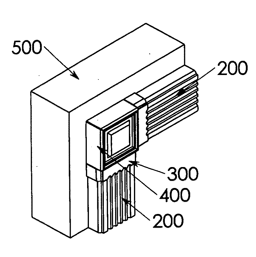
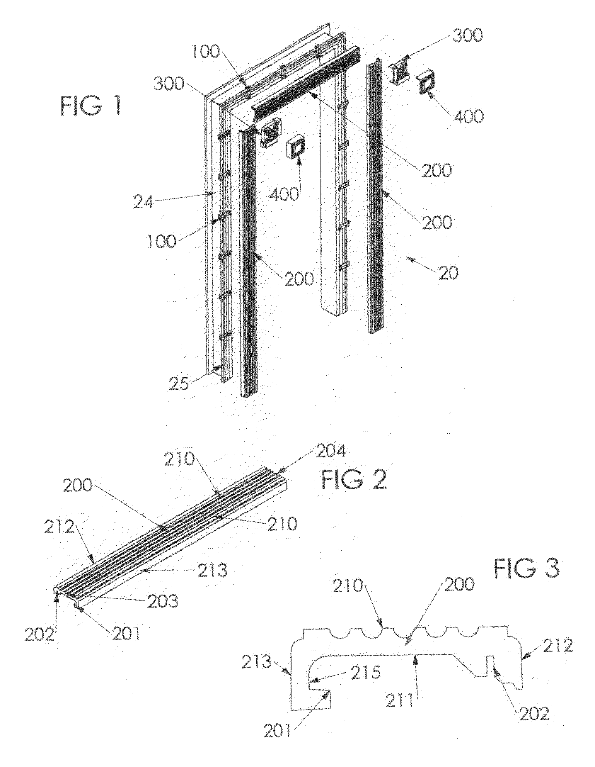
[0043]In FIG. 1, a typical installation of retrofit decorative molding system 20 of the present invention is provided, depicting the complete assembly of molding system 20 to a door frame. In FIGS. 1, a door frame is depicted for exemplary purposes only, and it should be understood that virtually a identical retrofit decorative molding sys...


PUM


Abstract

By providing a plurality of supporting clips which are quickly and easily mounted to the existing molding of a doorway or window frame and are constructed for receiving and supportingly retaining elongated, longitudinally extending decorative panels which are formed from a wide variety of decorative and visually distinctive appearances, a retrofit decorative molding system is achieved which is capable of being quickly and easily installed to any desired existing frame assembly by any unskilled individual, without requiring the use of mitered corners, abutting junctures, nails, adhesives, and the like. In addition, corner forming elements are employed to complete the construction. Furthermore, disassembly or removal of the existing components is required. By employing the combination of the components of the present invention, any desired frame assembly can be quickly and easily retrofitted with a completely installed decorative molding system for enhancing the visual and aesthetic appeal of any room or building.

Description

RELATED APPLICATIONS[0001]This application is related to U.S. Provisional Patent Application Ser. No. 60 / 993,512, filed Sep. 11, 2007 entitled RETROFIT SYSTEM FOR DOORS, WINDOWS AND FRAMED OPENINGS.TECHNICAL FIELD[0002]This invention relates to molding systems for installation in homes, offices, and other buildings and, more particularly, to retrofit decorative molding systems which are quickly and easily mounted in position directly over existing molding elements without requiring the use of adhesives, nails, other similar fastening elements.BACKGROUND ART[0003]Individuals are continuously upgrading their residences and / or offices in order to improve the visual appeal of their homes or businesses. Frequently, these upgrades include decorative or aesthetic improvements or enhancements which are employed for making homes / businesses more visually attractive both for the owner as well as for resale of the home / business. In addition, similar improvements or enhancements are also employe...

Claims


Application Information

Patent Timeline
Patent Type & Authority Applications(United States)
IPC IPC(8): E06B1/34
CPCE04F19/0463E06B2003/6291E06B1/34E04F19/0495
Inventor OUYANG, TIANHONGROBINSON, KENNETH L.STOCKS, BOBBY A.
Owner FOCAL POINT PRODS
Why Eureka
Try Eureka