Blast treatment method and blast treatment device

a treatment method and a technology of a blast treatment device, applied in the direction of weapons, ammunition, weapon components, etc., can solve the problems of increasing the risk of scattering outward of shell fragments, most chemical agents are decomposed under ultra-high temperature and ultra-high pressur

Inactive Publication Date: 2012-06-07
KOBE STEEL LTD
View PDF2 Cites 8 Cited by
  • Summary
  • Abstract
  • Description
  • Claims
  • Application Information

AI Technical Summary

Benefits of technology

[0010]According to the method wherein the detonation of the outside explosive is simultaneously initiated at the plurality of positions thereof spaced from each other at predetermined intervals along the particular direction so that the detonation of the inside explosive is simultaneously triggered at the plurality of positions thereof along the particular direction, the treatment subject is blasted in such a manner that the detonations of the inside explosive are completed before the detonation of the bursting charge initiated by the detonations of the inside explosive is completed. Therefore, a detonation vector of the inside explosive directed inward is propagated to the bursting charge not yet detonated, which ensures that a detonation vector of the bursting charge is directed inward. This effectively prevents fragments of the treatment subject from scattering outward.

Problems solved by technology

Further, when bombs including chemical agents hazardous to human bodies are treated by the treatment method, most of the chemical agents are decomposed under the ultra-high temperature and ultra-high pressure generated by explosion.
Then, the bursting charge detonates before the ANFO explosive provided on its outer side detonates, and as a result, it increases the risk of scattering the shell fragments outward.Patent Document 1: Japanese Patent Application Publication No. 2005-291514

Method used


Image

  • Blast treatment method and blast treatment device
  • Blast treatment method and blast treatment device
  • Blast treatment method and blast treatment device

Examples


Embodiment Construction

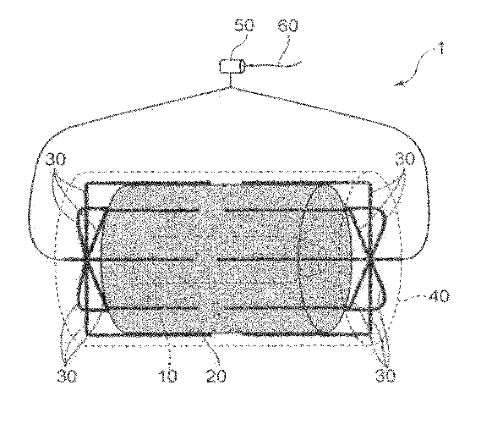
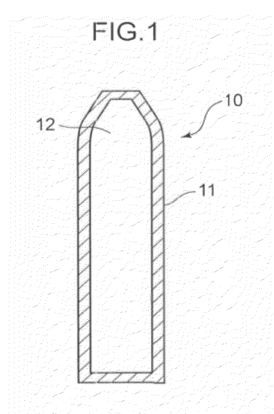
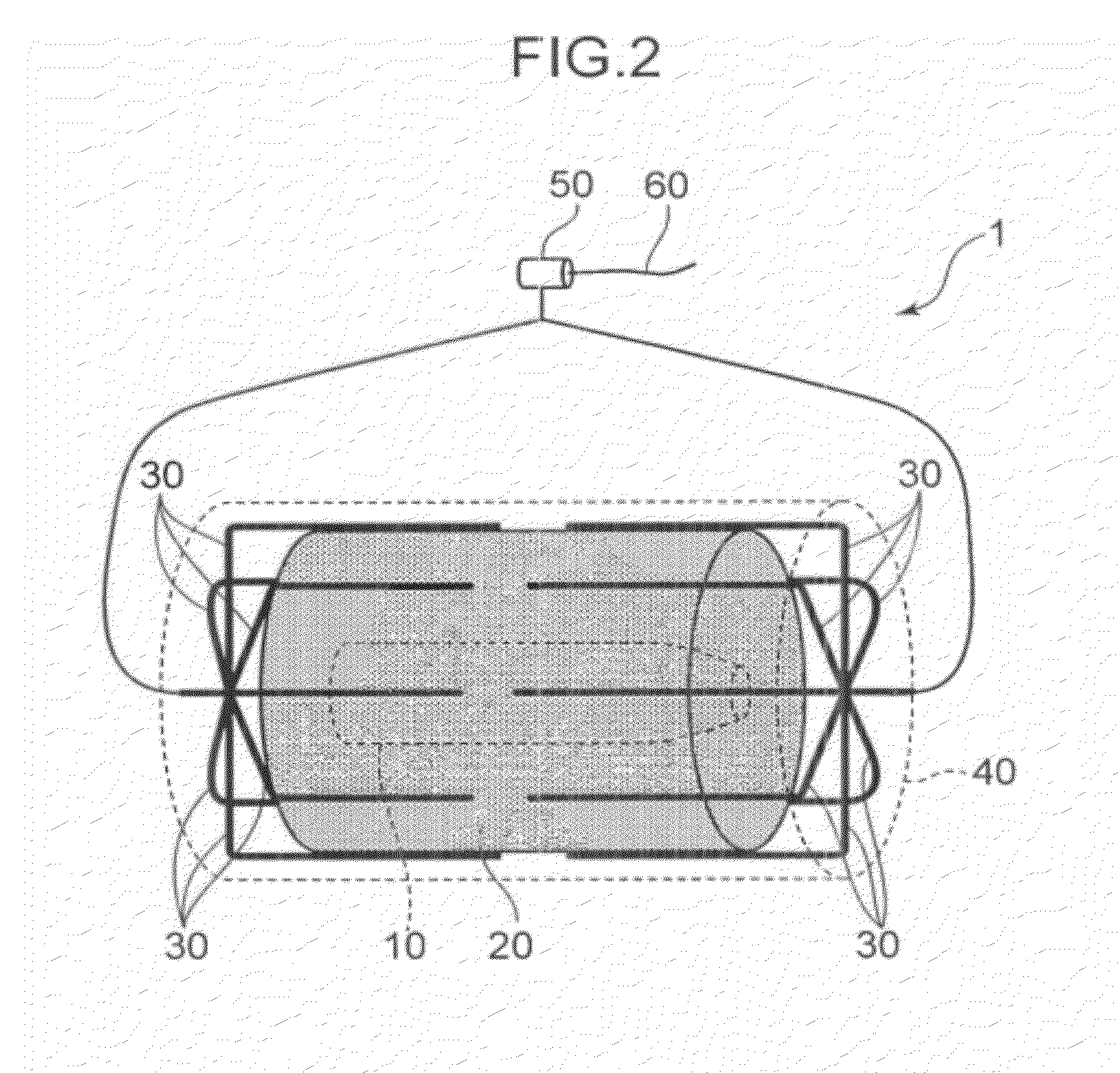
[0017]Hereinafter, an embodiments of a blast treatment method according to the present invention are described in detail referring to the accompanied drawings. FIG. 1 is a sectional view of a conventional munition 10 which is a treatment subject. FIG. 2 is a perspective view of a blast treatment device to which the blast treatment method according to the present invention is applied. FIG. 3 is a longitudinal sectional view of the blast treatment device. FIG. 4 is a cross-sectional view of the blast treatment device.

[0018]As illustrated in FIG. 1, the conventional munition 10 has such a shape that axially extends. The conventional munition 10 has a shell 11 made of steel and a bursting charge 12.

[0019]Examples of a material of the bursting charge 12 are TNT and picric acid. When the bursting charge 12 is initiated by a fuze not illustrated in the drawings to blast, the shell 11 is broken, and fragments of the shell 11 are scattered around.

[0020]For example, as illustrated in FIG. 2, ...


PUM


Abstract

Provided is a blast treatment method that can be implemented simply and efficiently blast a treatment subject while preventing fragments of the subject from scattering outward. The blast treatment method is used to blast a treatment subject 10 having a bursting charge 12 and a shell 11, and includes: an inside explosive disposing step of arranging an inside explosive 20 to be used to blast the treatment subject 10 around the treatment subject 10; an outside explosive disposing step of arranging an outside explosive 34 having a greater detonation velocity than the inside explosive 20 at positions on an outer side of the inside explosive 20; and a blast step of simultaneously initiating detonation of the outside explosive 34 at a plurality of positions spaced from each other at predetermined intervals along a particular direction to thereby simultaneously initiate detonations of the inside explosive 20 at a plurality of positions along the particular direction by the detonation of the outside explosive 34, and thereby blasting the treatment subject in such a manner that the detonations of the inside explosive 20 are completed before the detonation of the bursting charge 12 initiated by the detonations of the inside explosive 20 is completed.

Description

TECHNICAL FIELD[0001]The present invention relates to a blast treatment method and a blast treatment device by which an explosive subject, such as military ammunition, is blasted to be disposed of.BACKGROUND ART[0002]The military ammunition (for example, artillery shells, bombs, landmines, and underwater mines) generally has a structure where a shell made of steel contains therein a bursting charge.[0003]The ammunition is treated by blasting, for example. The treatment method by blasting requires no disassembling operation. This provides adaptability to a disposal not only of favorably preserved munitions, for example, but also of munitions hard to disassemble because of its deterioration over time, deformation, or the like. Further, when bombs including chemical agents hazardous to human bodies are treated by the treatment method, most of the chemical agents are decomposed under the ultra-high temperature and ultra-high pressure generated by explosion. An example of such a blast tr...

Claims


Application Information

Patent Timeline
Patent Type & Authority Applications(United States)
IPC IPC(8): F42B33/06F42D5/04
CPCF42D5/04F42D3/00F42B33/06
Inventor KOIDE, KENJIKITAMURA, RYUSUKELEFEBVRE, MICHEL H.
Owner KOBE STEEL LTD
Why Eureka
Try Eureka