Light source unit and projector

a technology of light source unit and projector, which is applied in the direction of instruments, lighting and heating apparatus, spectral modifiers, etc., can solve the problems of complex optical layout, increased lenses and mirrors, and complex optical layou

Active Publication Date: 2012-06-07
CASIO COMPUTER CO LTD
View PDF10 Cites 33 Cited by
  • Summary
  • Abstract
  • Description
  • Claims
  • Application Information

AI Technical Summary

Benefits of technology

[0014]The invention has been made in view of the problems inherent in the related art, and an object thereof is to provide a small light source unit and a projector which includes the small light source unit.
[0015]According to a first aspect of the invention, there is provided a light source unit including: a laser light source unit in which two types of laser emitting elements which emit light of different wavelength bands each other are arranged in a planar fashion; a diffusing unit disposed on an optical path of light emitted from the laser light source unit to diffuse light emitted from the laser light source unit; and a light source control unit which time-share controls the illumination of the laser emitting elements.
[0016]According to a second aspect of the invention, there is provided a projector comprising: the light source unit set forth in the first aspect; a display device which generates projection light; a light source side optical system which guides light emitted from the light source unit to the display device; a projection side optical system which guides projection light generated in the display device; and a projector control unit which controls the display device and the light source unit.

Problems solved by technology

Therefore, the optical layout becomes complex when attempting to cause the directions of optical axes of light of red wavelength band, light of green wavelength band and light of blue wavelength band to coincide with each other so as to be shone on to the display device.
In addition, the optical layout becomes complex, and therefore, the numbers of lenses and mirrors are increased, which disturbs the attempt to reduce the production costs, as well as to make the projector small in size.
Consequently, the solutions to the complex layout and the attempt to increase the quantity of light of red wavelength band cause disturbance to ensuring the degree of freedom in designing projectors which are small in size and which consume less electric power.

Method used


Image

  • Light source unit and projector
  • Light source unit and projector
  • Light source unit and projector

Examples


Embodiment Construction

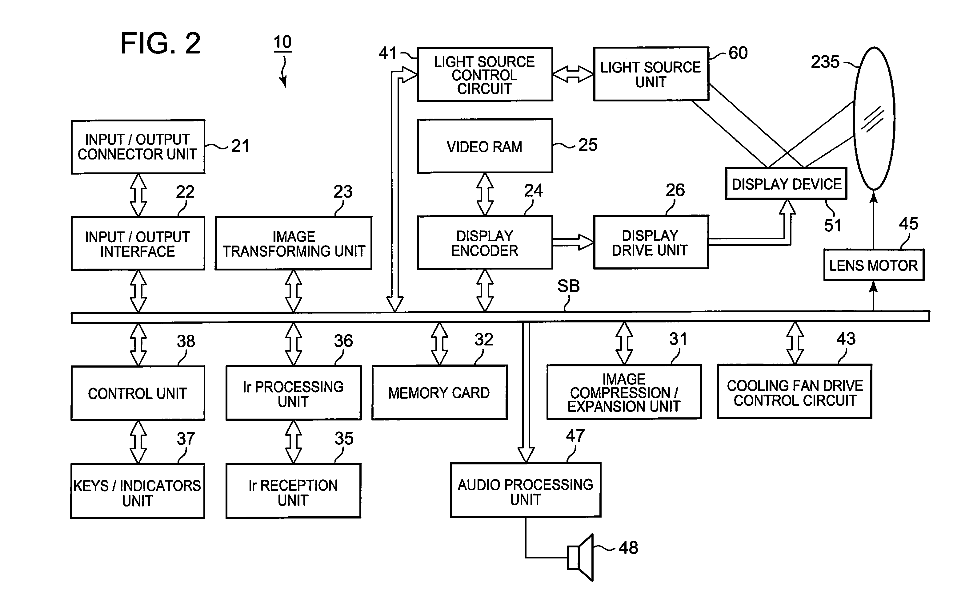
[0027]Hereinafter, embodiment for carrying out the invention will be described by reference to the accompanying drawings.

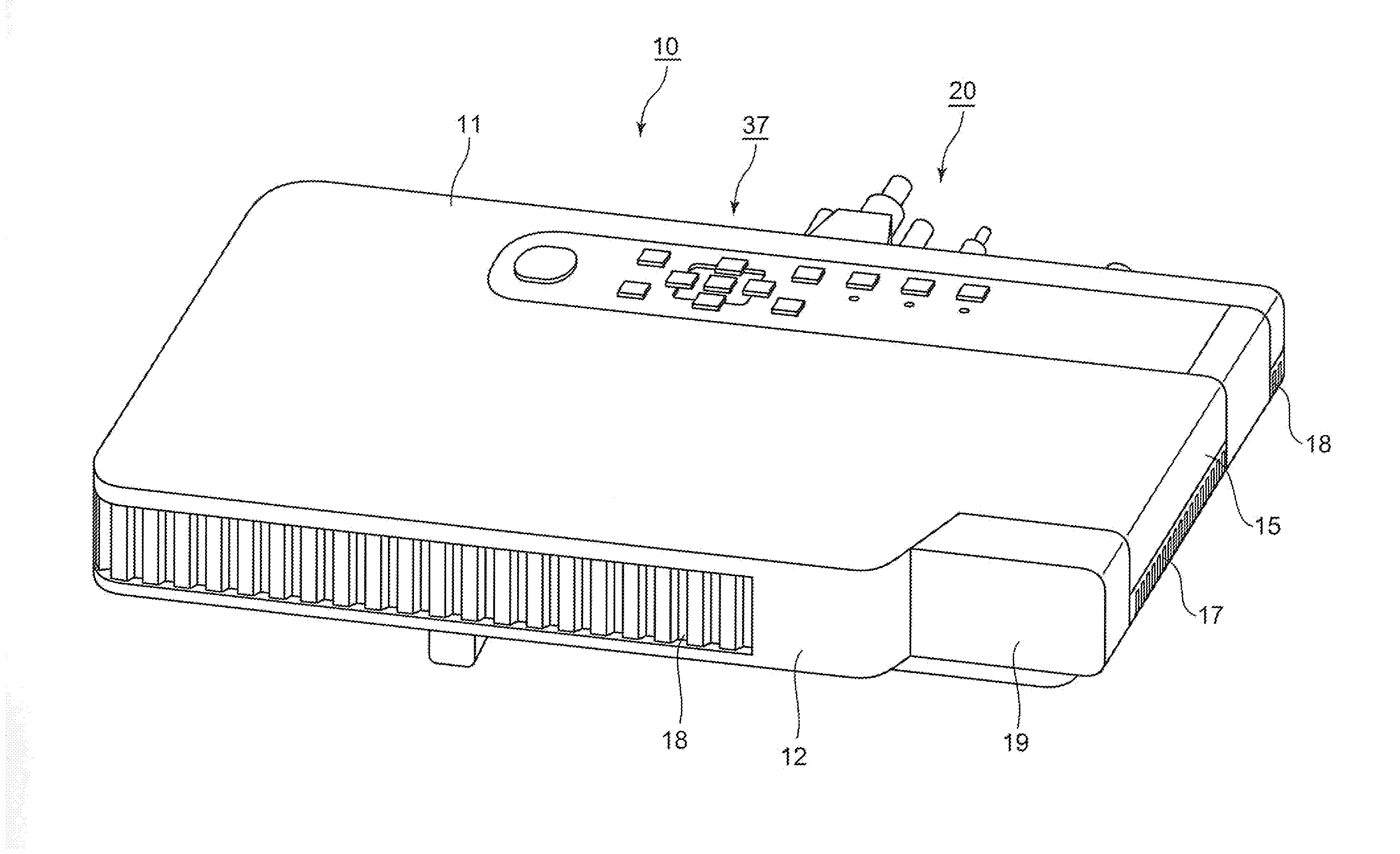
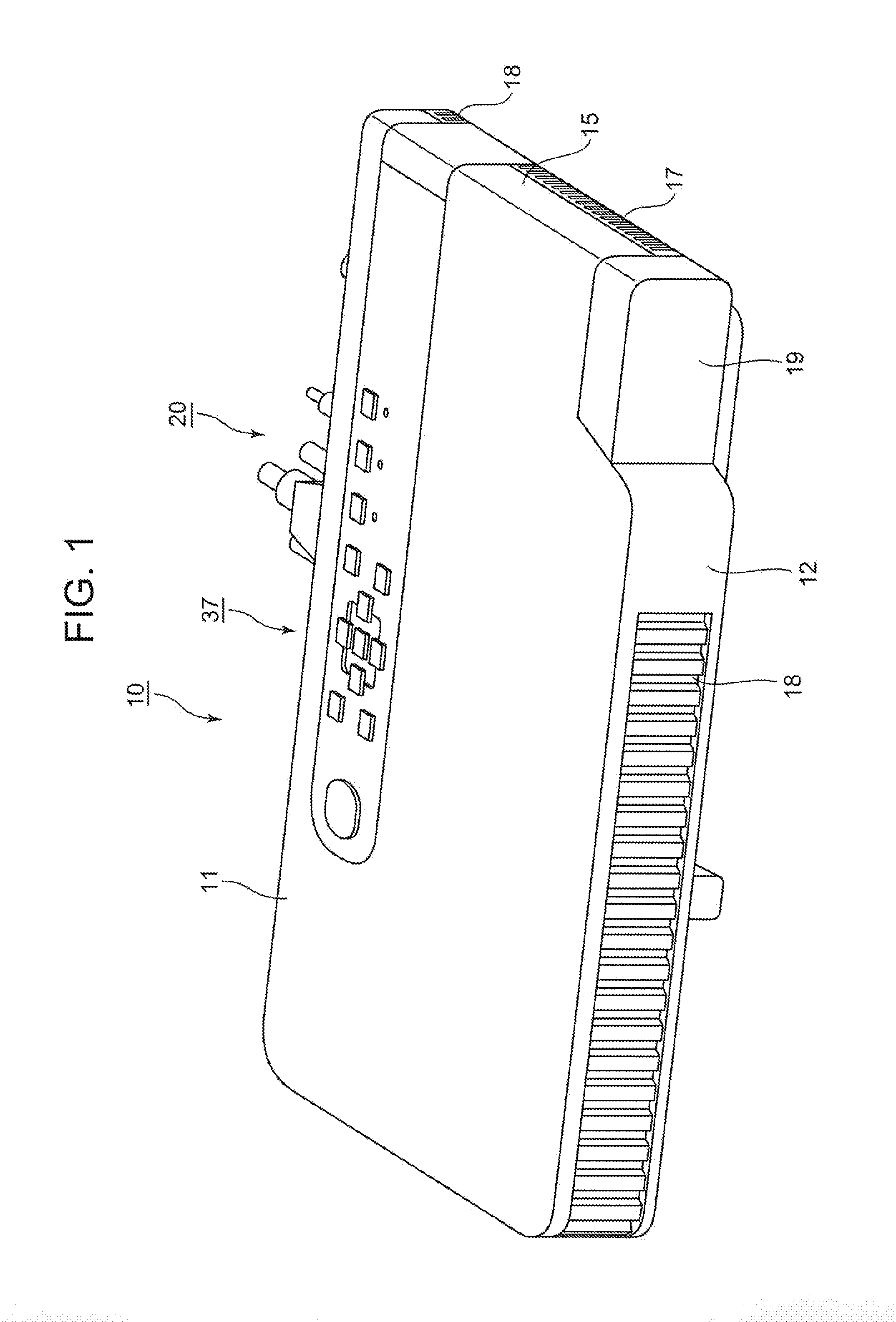
[0028]FIG. 1 is a perspective view showing an external appearance of a projector 10.

[0029]In this embodiment, left and right with respect to the projector 10 denote, respectively, left and right directions with respect to a projecting direction, and front and rear denote, respectively, front and rear directions with respect to a direction towards a screen and a traveling direction of a pencil of light.

[0030]As is shown in FIG. 1, the projector 10 according to the embodiment has a substantially rectangular parallelepiped shape and has a lens cover 19 which covers a projection port which is laid to a side of a front panel 12 which is referred to as a front side panel of a main body casing, and the front panel 12 has a plurality of outside air inlet ports 18.

[0031]Further, although not shown, the projector 10 includes an Ir reception unit which is mounted in the fron...


PUM


Abstract

A projector is provided which includes a light source unit which can reduce the numbers of lenses and mirrors and which can control quantity of light of each color.
A light source unit of the invention includes a laser light source unit 70 which has a plurality of red laser elements 71R and a plurality of blue laser elements 71B as two types of laser emitting elements 71 which emit light of wavelength bands which are different from each other and in which the pluralities of red and blue laser emitting elements 71R, 71B are arranged in a planar fashion, a diffusing unit which is disposed on an optical path of light emitted from the laser light source unit 70 to diffuse the light emitted from the laser light source unit 70, and a light source control unit for controlling the illumination of the laser emitting elements 71R, 71B.

Description

CROSS-REFERENCE TO RELATED APPLICATIONS[0001]This application is based upon and claims the benefit of priority under 35 USC 119 of Japanese Patent Application No. 2010-272414 filed on Dec. 7, 2010, the entire disclosure of which, including the description, claims, drawings and abstract thereof, is to be incorporated herein by reference.BACKGROUND OF THE INVENTION[0002]1. Field of the Invention[0003]The present invention relates to a light source unit and a projector.[0004]2. Description of the Related Art[0005]In these days, data projectors are used on many occasions as image projection apparatuses which project images including images of screens of personal computers and video images, as well as images based on image data which is stored in memory cards on to a screen.[0006]Conventionally, the mainstream of these projectors has been those which use a high-intensity discharge lamp as a light source. However, in recent years, there have been made many developments and proposals on pr...

Claims


Application Information

Patent Timeline
Patent Type & Authority Applications(United States)
IPC IPC(8): G03B21/14F21V9/16F21V11/00
CPCG03B21/2093G03B21/204G03B21/20
Inventor MASUDA, HIROKI
Owner CASIO COMPUTER CO LTD
Why Eureka
Try Eureka