Dual arm robot

a robot and arm technology, applied in the field of dual arm robots, can solve the problem that the robot cannot be used in a vacuum transport module built per semi-mesc standards

Active Publication Date: 2012-06-07
BOOKS AUTOMATION US LLC
View PDF3 Cites 100 Cited by
  • Summary
  • Abstract
  • Description
  • Claims
  • Application Information

AI Technical Summary

Problems solved by technology

This robot, however, cannot be used in a vacuum transport module built per SEMI MESC standards, because the isolation valves of such a vacuum transport module are too narrow to allow passage of the arm that includes the C-type bracket per the SEMI specification that defines wafer transport planes within cassette and process modules.

Method used


Image

  • Dual arm robot
  • Dual arm robot
  • Dual arm robot

Examples


Embodiment Construction

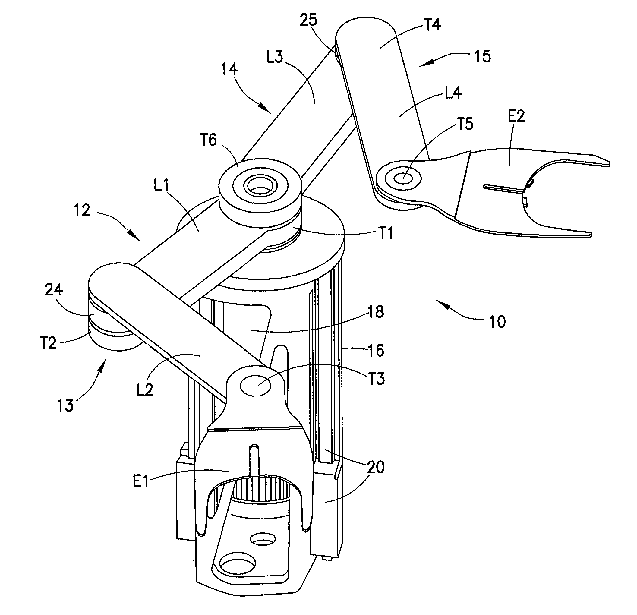
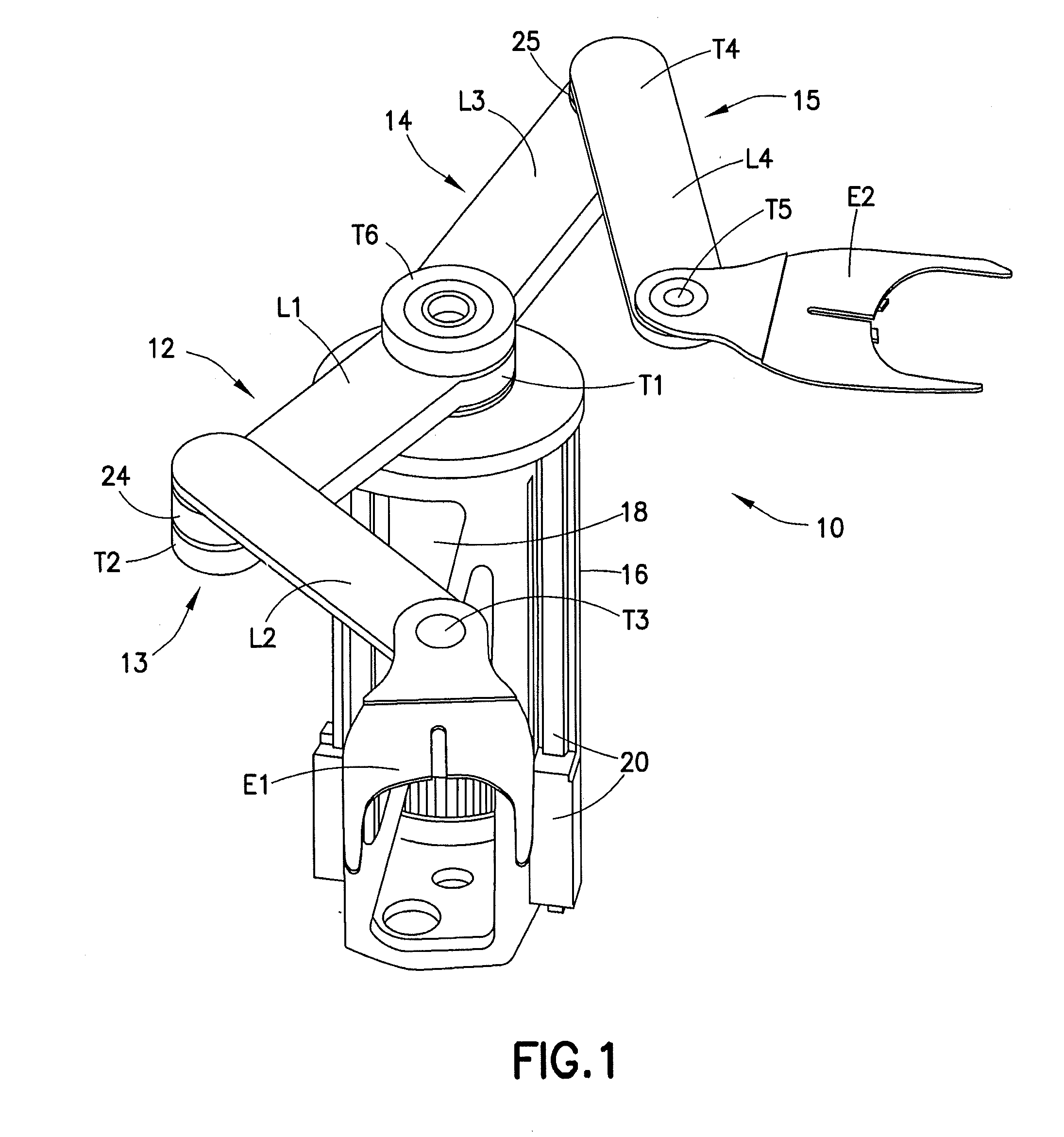
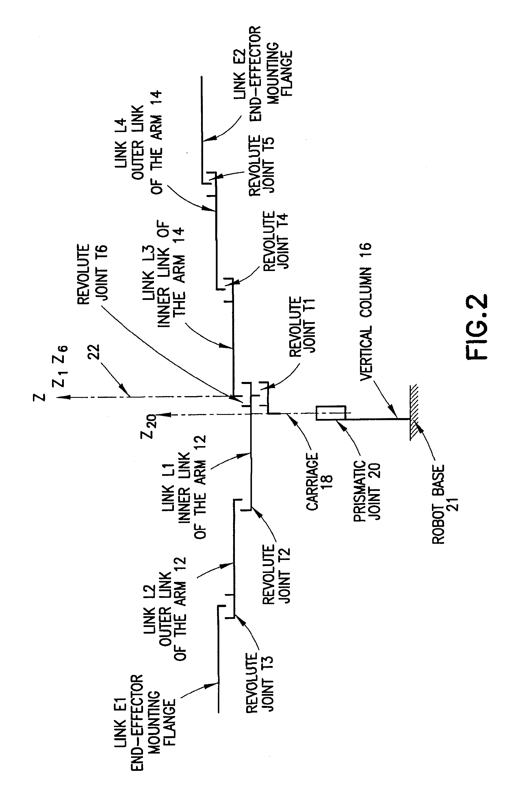
[0042]The aspects of the disclosed embodiment relate to a dual arm, cylindrical coordinate robot assembly, and more particularly to the manipulator, the system of links and joints that cooperate to position a pair of end effectors, for such a robot assembly. It is noted that suitable examples of dual arm robot assemblies can be found in U.S. patent application Ser. No. 13 / 030,856, filed on Feb. 18, 2011 which is a divisional application of U.S. patent application Ser. No. 10 / 434,582, filed May 09, 2003 and United States Provisional Patent Application Nos. 60 / 378,983, 60 / 379,095 and 60 / 379,063 both filed on May 9, 2002, the disclosures of which are all incorporated by reference herein in their entireties.

[0043]For purposes of describing the aspects of the disclosed embodiment, the manipulator can be described as a mechanical assembly and broken down into major linkages, minor linkages (wrist components), and the end effector. The major linkages are the set of joint-link pairs that po...


PUM


Abstract

A substrate processing apparatus including a frame, a first arm coupled to the frame at a shoulder axis having a first upper arm, a first forearm and at least one substrate holder serially and rotatably coupled to each other, a second arm coupled to the frame at the shoulder axis where shoulder axes of rotation of the arms are substantially coincident, the second arm having a second upper arm, a second forearm and at least one substrate holder serially and rotatably coupled to each other, and a drive section connected to the frame and coupled to the arms, the drive section being configured to independently extend and rotate each arm where an axis of extension of the first arm is angled relative to an axis of extension of the second arm substantially at each angular position of at least one of the first arm or the second arm.

Description

CROSS REFERENCE TO RELATED APPLICATIONS[0001]This application is a non-provisional of and claims the benefit of U.S. Provisional Patent Application No. 61 / 412,218 filed on Nov. 10, 2010 and U.S. Provisional Patent Application No. 61 / 451,912 filed on Mar. 11, 2011, the disclosures of which are all incorporated herein by reference in their entireties.BACKGROUND OF THE INVENTION[0002]Robots are used to perform many tasks in the semiconductor industry, such as the automated handling of substrate media or other objects. In the semiconductor industry, typical media and other objects include individual silicon wafers or wafer carriers, flat panel displays, and hard disk media. Robots may be used for handling media in, for example, wafer processing cluster tools, wafer inspection equipment, metrology equipment, and equipment for hard disk thin film deposition, and in transferring media between production equipment and automated material handling systems in semiconductor factories. Robots ma...

Claims


Application Information

Patent Timeline
Patent Type & Authority Applications(United States)
IPC IPC(8): H01L21/677
CPCB25J9/042B25J9/043B25J11/0095H01L21/67742H01L21/68771
Inventor KRUPYSHEV, ALEXANDER G.CAVENEY, ROBERT T.ELLIOT, MARTIN R.HOFMEISTER, CHRISTOPHER
Owner BOOKS AUTOMATION US LLC
Why Eureka
Try Eureka