
Watertight, Expandible and Contractible Pipe Joint for High Temperature Insulated Piping

a technology of expandible and contractible pipes and insulated pipes, which is applied in the direction of metal working equipment, manufacturing tools, mechanical equipment, etc., can solve the problems of pipe wetness with the same problems, damage to the hot bellows, and high temperatures that can affect the bonded foam system

Inactive Publication Date: 2012-06-14
THERMACOR PROCESS
View PDF12 Cites 8 Cited by
  • Summary
  • Abstract
  • Description
  • Claims
  • Application Information

AI Technical Summary

Benefits of technology

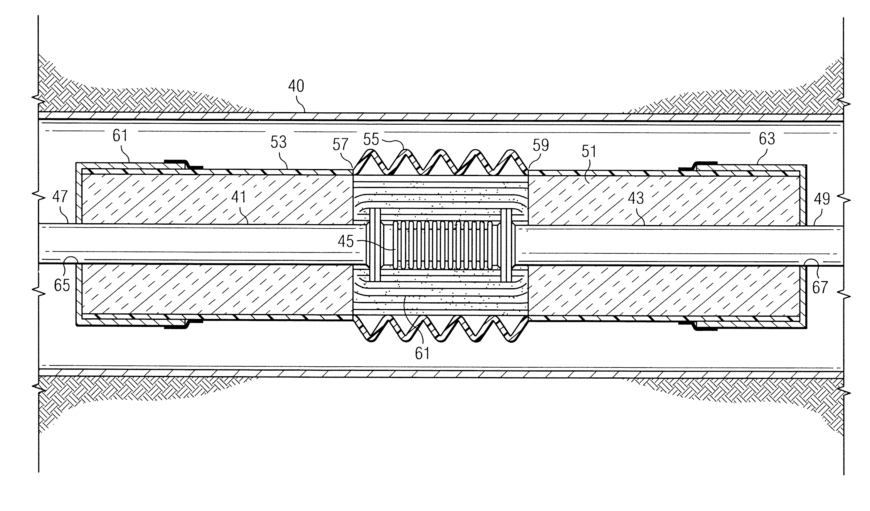
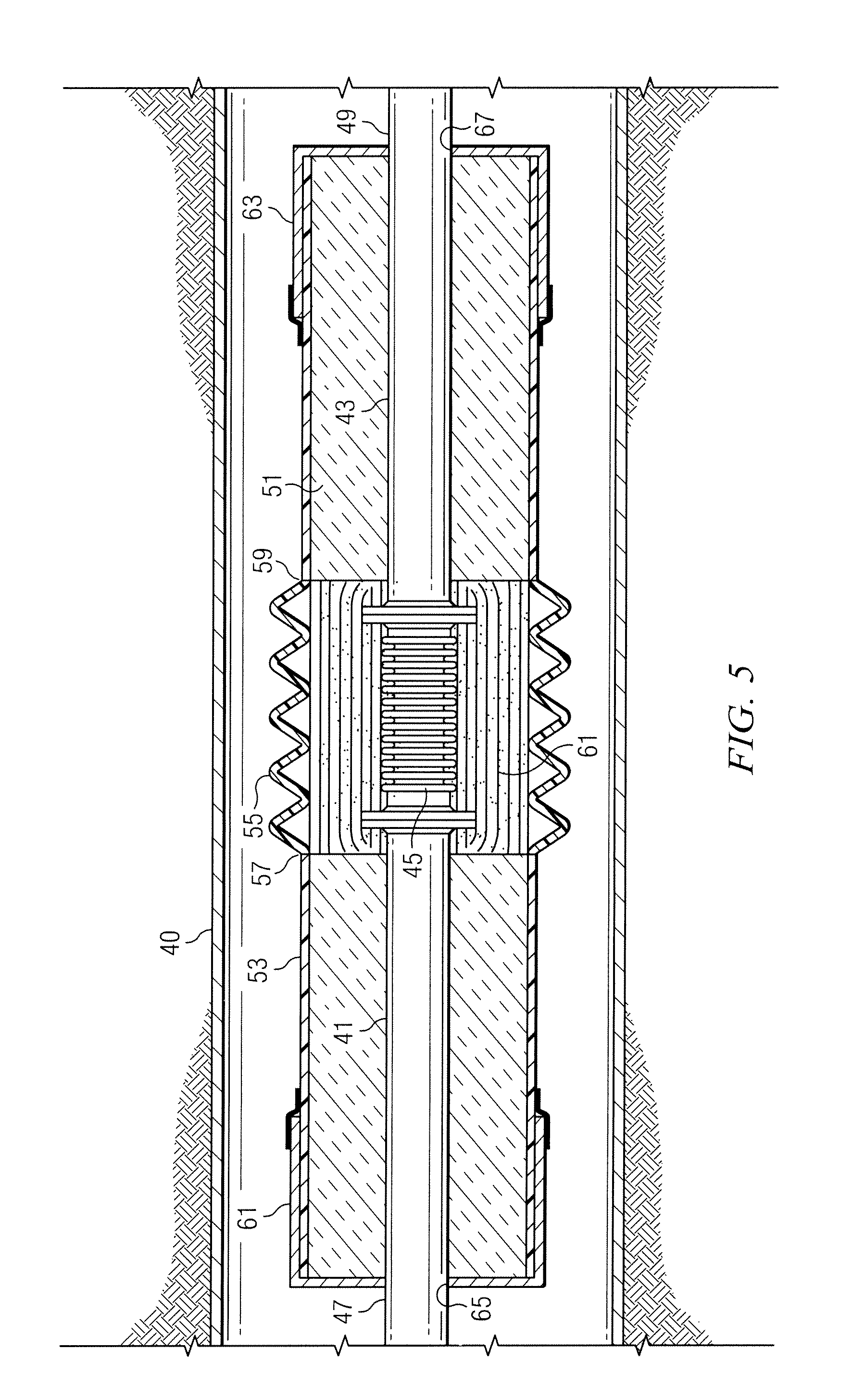
The present invention provides a pre-manufactured bellows joint for high temperature line expansion installations that solves the deficiencies of prior art systems. The watertight, expandable and contractible pipe joint includes inner metal carrier pipes, an envelope of bonded foam insulation, and an outer protective jacket. A flexible tubular bellows surrounds the inner ends of the inner pipes and the metallic expansion joint in a radially spaced apart fashion and is capable of being axially expanded and contracted. The pipe joint has a metal end cap or a metal water stop for watertight installation in high temperature insulated piping. The invention provides a stand-alone pipe joint that can be installed in a run of bare or field insulated piping. The foam insulation and protective jackets form a water tight encasement for the metallic expansion joint. The invention allows for continuous and secure conveyance of high temperature fluids.

Problems solved by technology

Higher temperatures can act adversely upon the bonded foam system, however.
Flood waters reaching the uninsulated metallic expansion bellows caused damage to the hot bellows, usually requiring that the joint be replaced or repaired.
Usually the piping is located in a high enough location to be kept dry, but high seas, hurricane conditions, etc. can cause the pipe to become wet with the same problems being encountered as in the case of flooded tunnels.

Method used


Image

  • Watertight, Expandible and Contractible Pipe Joint for High Temperature Insulated Piping
  • Watertight, Expandible and Contractible Pipe Joint for High Temperature Insulated Piping
  • Watertight, Expandible and Contractible Pipe Joint for High Temperature Insulated Piping

Examples


Embodiment Construction

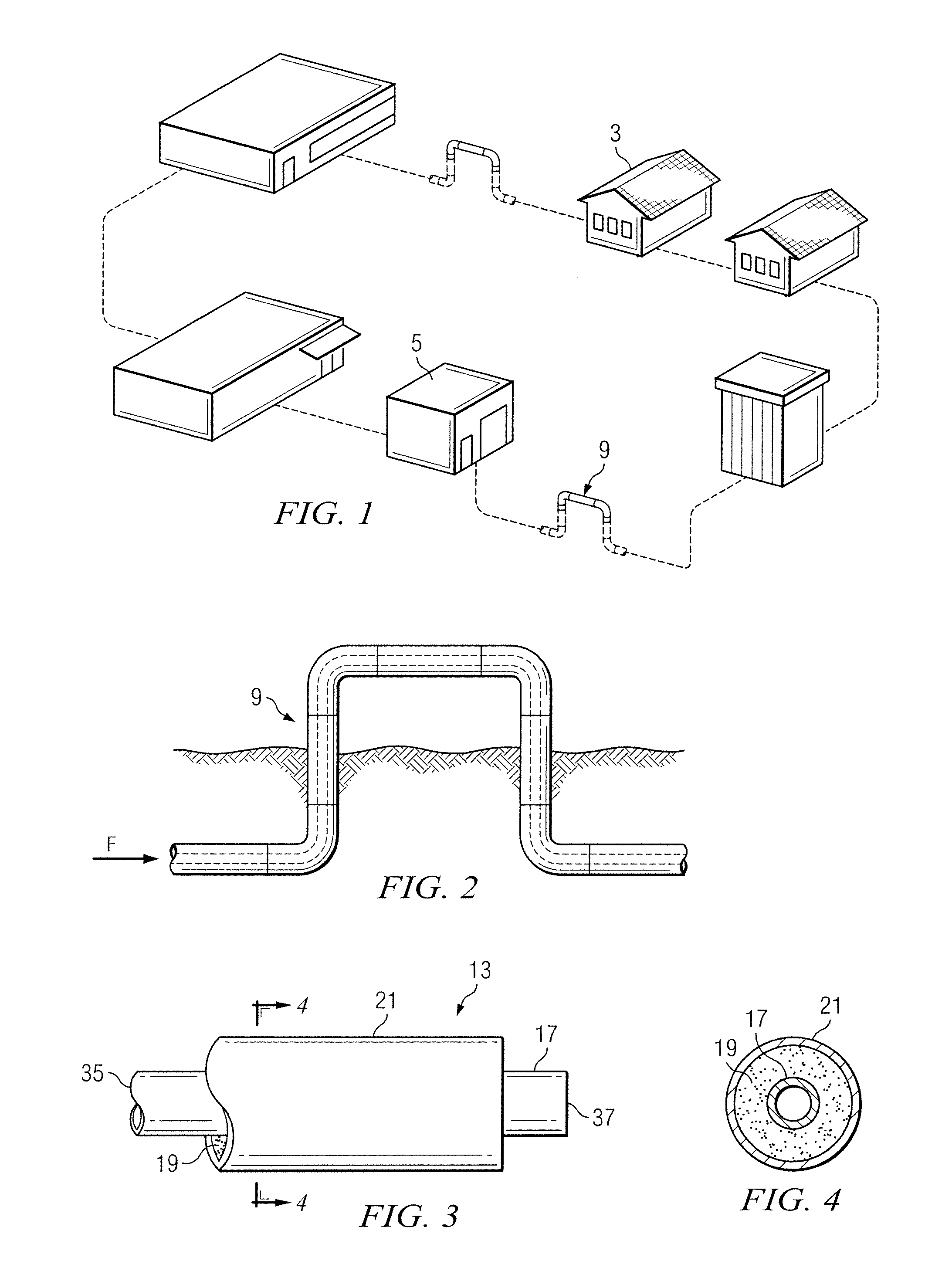
[0031]Turning first to FIGS. 1-4, there is shown a typical environment in which a pre-insulated piping system of the type used to convey high temperature fluids might be employed. FIG. 1 shows a school campus having a number of isolated buildings 3, 5, connected by an underground insulated pipeline carrying steam which at points includes right angle loops or elbows 9. FIG. 2 shows one of the expansion loops 9 in greater detail. Loops of this type might be installed at various locations along the run of piping to accommodate expansion and contraction forces in the pipeline caused by, for example, changes in temperature. These types of expansion loops perform well in many situations with underground piping systems. However, they require a certain amount of space to install. In the case of insulated piping systems run through confined spaces, such as for example tunnel installations, there may not be adequate space for expansion loops.

[0032]FIGS. 3 and 4 show a typical joint of bonded ...


PUM

PropertyMeasurementUnit
temperatureaaaaaaaaaa
temperaturesaaaaaaaaaa
lengthaaaaaaaaaa

Abstract

An expansion joint is shown for an insulated pipeline used to convey high temperature fluids such as steam. The expansion joint uses a flexible bellows and additional insulating and joining components to provide a watertight encasement for a traditional metal expansion joint. The bellows arrangement compensates for any relative movement of the inner fluid conveying pipes with respect to the outer layers of insulating material and outer jacket in order to protect the integrity of the assembly and prevent the intrusion of water or other contaminants which could lead to corrosion or early failure of the piping system.

Description

CROSS-REFERENCE TO RELATED APPLICATION[0001]The present application claims priority from Provisional Application Ser. No. 61 / 422,500, filed Dec. 13, 2010 by the same inventor.BACKGROUND OF THE INVENTION[0002]1. Field of the Invention[0003]The present invention relates to insulated piping systems of the type used to convey high temperature fluids and, more specifically, to an expansion joint for such piping systems which counteracts the tendency of the carrier pipe in these systems to move as the systems thermally expand and contract in the presence of high temperature fluids being conveyed.[0004]2. Description of the Prior Art[0005]There are many instances in which insulated pipelines are needed. For example, distributed HVAC (heating, ventilation and air conditioning) applications utilize chilled water for cooling and steam for heating. The chiller and boiler are typically contained in a central location and the chilled water and steam are distributed to other locations. For exampl...

Claims


Application Information

Patent Timeline
Patent Type & Authority Applications(United States)
IPC IPC(8): F16L55/00B23P11/00
CPCY10T29/49826F16L59/21
Inventor KEYES, THOMAS JOSEPH
Owner THERMACOR PROCESS
Learn More