Nail print apparatus

a nail print and nail technology, applied in the field of nail print apparatus, can solve the problems of printing errors, inability to finely print graphics, and movement of the printing finger, and achieve the effect of accurate printing, preventing upward bending, and printing fingers

Active Publication Date: 2012-06-14
CASIO COMPUTER CO LTD
View PDF2 Cites 53 Cited by
  • Summary
  • Abstract
  • Description
  • Claims
  • Application Information

AI Technical Summary

Benefits of technology

[0017]Therefore, by a simple manner of respectively inserting the printing fingers in the finger insertion members, the printing fingers can be prevented from bending upward while fixing the nail portions of the printing finger at positions near the printing section as much as possible, and nail printing can be performed accurately to the nail portion by the printing section. Further, breaking of the printing section due t

Problems solved by technology

However, when the printing finger is merely placed on the mounting table, there is a possibility that the printing finger may move due to movements of the hand and arm transmitting to the printing finger because the hand is in an unstable state.
When the printing finger moves during printing causing the position of the printing finger to shift, graphics cannot be printed accurately on the nail, thus causing printing error to occur.
Further, when printing is performed in an inkjet method, for example, graphics cannot be printed finely because ink cannot be applied to correct positions when the printing head of the printing device and the nail are too far apart from each other.
On the other hand, when the printing head and the nail are too close to each other, there is a possibility that the nail and finger may be smeared or the printing head may break due to the nail and finger contacting the printing head.
Therefore, when trying to perform printing to a plurality of fi

Method used


Image

  • Nail print apparatus
  • Nail print apparatus
  • Nail print apparatus

Examples


first embodiment

[0056]First, the first embodiment of a nail print apparatus according to the present invention will be described with reference to FIGS. 1 to 9. Note that the scope of the present invention will not be limited to the examples shown in the drawings.

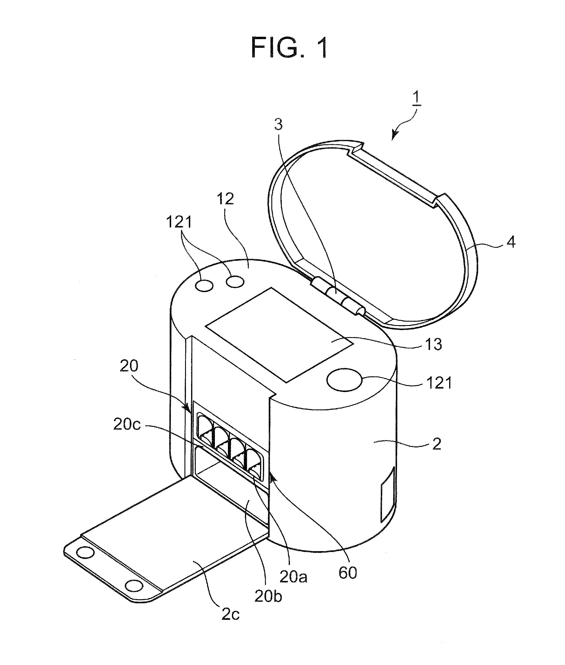
[0057]FIG. 1 is a schematic view showing an outer view of the nail print apparatus of this embodiment.

[0058]As shown in FIG. 1, the nail print apparatus 1 includes a case body 2 and a cover 4. The case body 2 and the cover 4 are joined to each other via a hinge 3 provided at the upper surface back end portion of the case body 2.

[0059]The case body 2 is formed in an oval shape in a plan view. An open / close plate 2c which can rise and fall is provided on the front of the case body 2. The open / close plate 2c is joined to the case body 2 via a hinge (not shown in the drawing) provided on the front surface at lower end portion of the case body 2. The open / close plate 2c is to open and close the front side of the case body 2.

[0060]Moreover, the ...

second embodiment

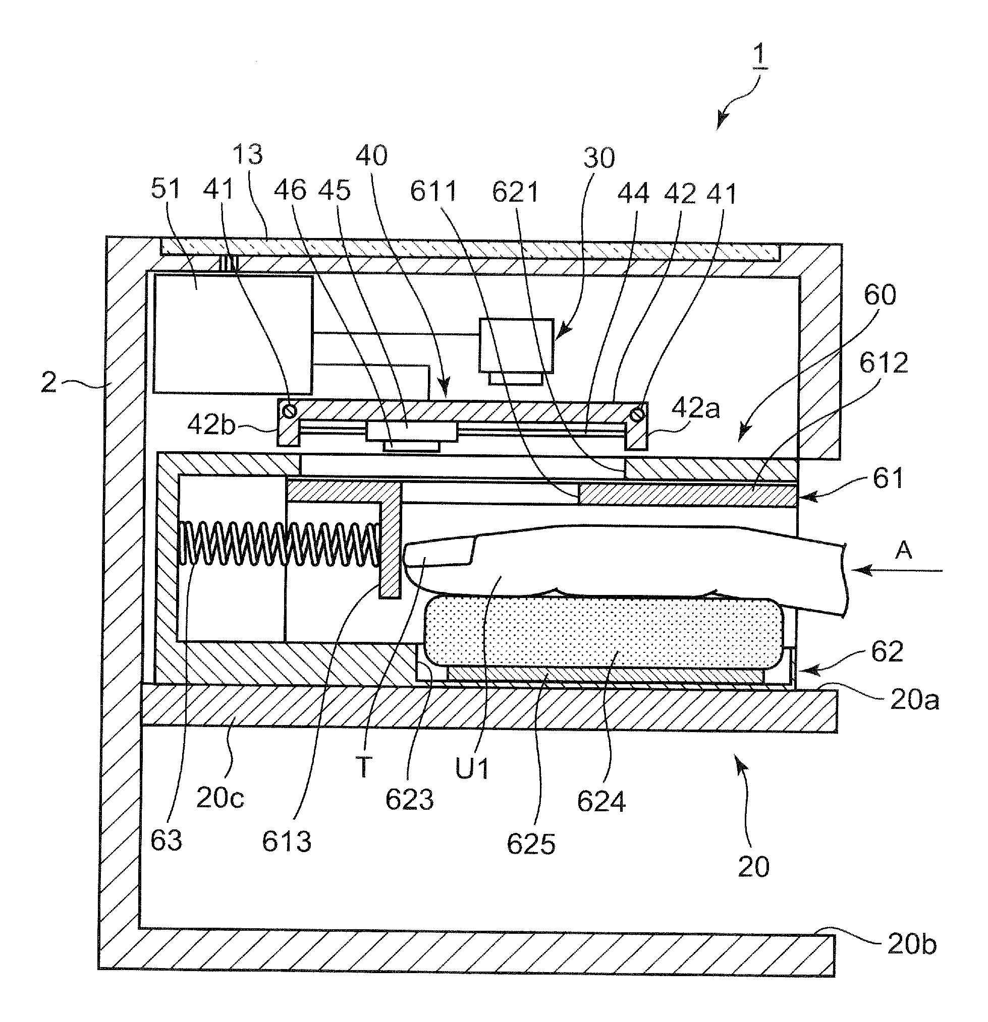
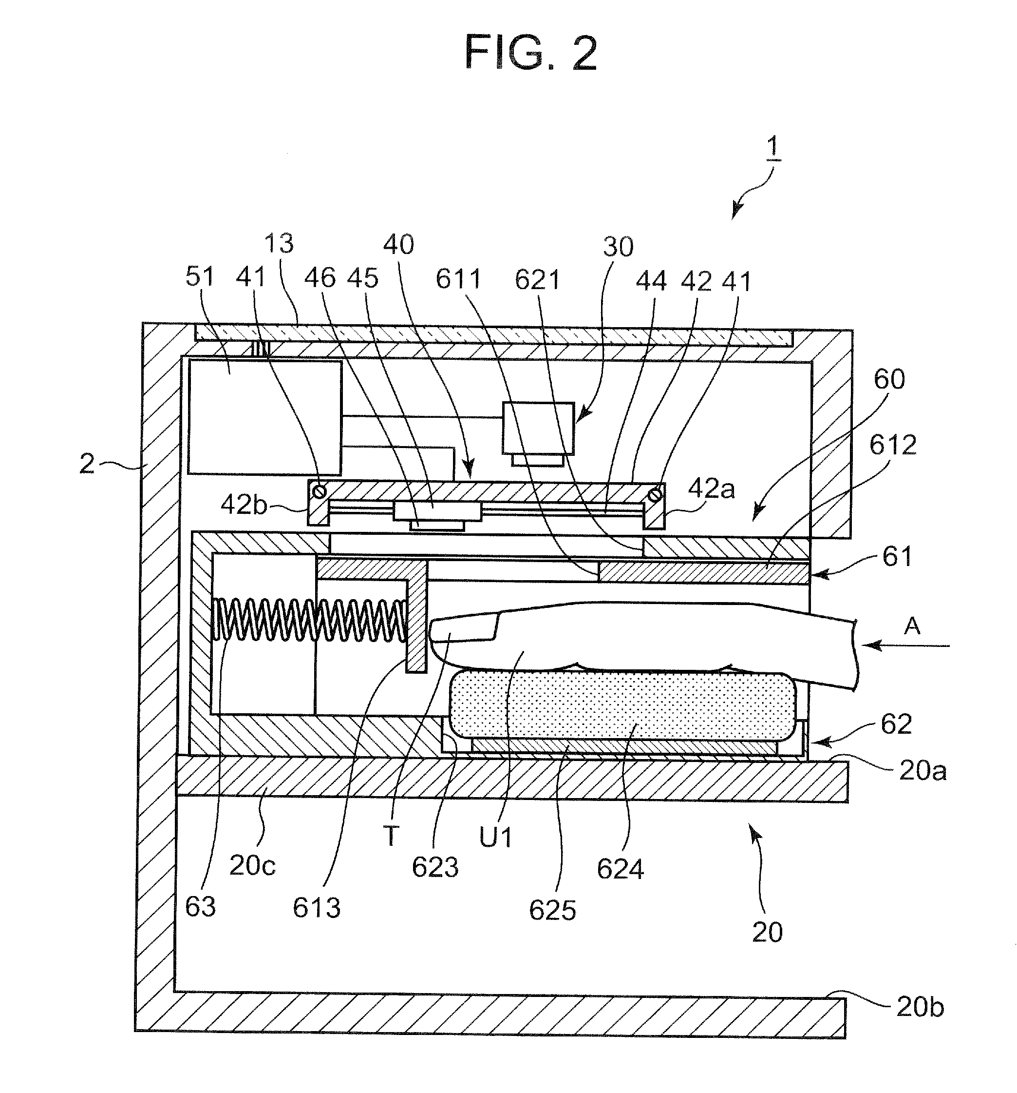
[0129]Next, the second embodiment of the nail print apparatus according to the present invention will be described with reference to FIGS. 10 and 11. Here, in this embodiment, only the configuration of the printing finger fixation unit is different from that in the first embodiment. Therefore, in the following description, only the aspects which are different from the first embodiment will be specifically described.

[0130]FIG. 10 is a sectional side view of the nail print apparatus 1 of this embodiment, and FIG. 11 is a sectional view of the printing finger fixation unit shown in FIG. 10 when seen from the finger inserting direction A.

[0131]In this embodiment, the printing finger fixation unit 70 includes four finger insertion members 61 in each of which a finger can be inserted and a supporting member 72 which supports the four finger insertion members 61. The configuration of the finger insertion members 61 is similar to that in the first embodiment. Therefore, same reference numer...

third embodiment

[0155]Next, the third embodiment of the nail print apparatus according to the present invention will be described with reference to FIGS. 12 to 14. Here, in this embodiment, only the configuration of the printing finger fixation unit is different from that in the first embodiment and the second embodiment. Therefore, in the following description, the aspects which are different from the first embodiment and the second embodiment will be specifically described.

[0156]FIG. 12 is a sectional side view of the printing finger fixation unit of this embodiment, FIG. 13 is a sectional view cut along the line XIII-XIII in FIG. 12 and FIG. 14 is a sectional view cut along the line XIV-XIV in FIG. 12.

[0157]In this embodiment, the printing finger fixation unit 80 includes four finger insertion members 81 which are configured so that a finger can be inserted in each of them and a cover member 82 which houses the four finger insertion members 81.

[0158]As shown in FIGS. 12 to 14, in this embodiment...


PUM


Abstract

Disclosed is a nail print apparatus including a printing finger fixation section which fixes a printing finger and a printing section, and the printing finger fixation section includes at least on finger insertion member which is provided so as to slide along a finger inserting direction according to a length of the printing finger when the printing finger is inserted, and the finger insertion member includes a nail portion exposure window which is provided for exposing the nail portion in a side of the printing section, a finger pressing section for pressing a vicinity of a base of the nail portion from above when the printing finger is inserted, and an abutment member which is arranged in a back side in the finger inserting direction than the nail portion exposure window so that a tip portion of the printing finger abuts when the printing finger is inserted.

Description

BACKGROUND OF THE INVENTION[0001]1. Field of the Invention[0002]The present invention relates to a nail print apparatus.[0003]2. Description of Related Art[0004]Nail print apparatus is a printing apparatus which performs printing on a nail of a printing finger, wherein the printing finger which is a finger including the nail to which printing is to be performed being placed on a mounting table provided in the apparatus main body.[0005]However, when the printing finger is merely placed on the mounting table, there is a possibility that the printing finger may move due to movements of the hand and arm transmitting to the printing finger because the hand is in an unstable state. When the printing finger moves during printing causing the position of the printing finger to shift, graphics cannot be printed accurately on the nail, thus causing printing error to occur.[0006]Further, when printing is performed in an inkjet method, for example, graphics cannot be printed finely because ink c...

Claims


Application Information

Patent Timeline
IPC IPC(8): B41J2/01
CPCA45D29/00B41J3/407A45D2029/005A45D29/22
Inventor YAMASAKI, SHUICHI
Owner CASIO COMPUTER CO LTD
Why Eureka
Try Eureka