Solar light condensing system

a solar light and condenser technology, applied in solar heat systems, solar thermal energy generation, lighting and heating apparatus, etc., can solve the problems of difficult manufacturing of receivers, high manufacturing costs, and large size, and achieve the effect of suppressing power generation costs, facilitating recovery work, and suppressing manufacturing

Inactive Publication Date: 2012-06-21
MITSUI ENG & SHIPBUILD CO LTD
View PDF8 Cites 1 Cited by
  • Summary
  • Abstract
  • Description
  • Claims
  • Application Information

AI Technical Summary

Benefits of technology

[0029]The present invention can provide a sunlight collecting system achieving suppression of power generation cost with the receiver which enables suppressing the manufacturing, facilitating recovery work in the case of occurrence of a failure, and promptly recovering a heating medium circulating inside the receiver in an emergency.

Problems solved by technology

However, the pot-shaped receiver described in cited document 2 has a structure in which a single pipe is shaped into a pot shape, and thus faces problems that manufacturing the receiver is very difficult and the manufacturing costs are high.
In addition, the receiver is large in size, and thus transporting the receiver of an integrated type is not easy and constructing the receiver on site is a demanding work.
Further, a failure of the receiver such as a pipe breakage requires the entire receiver to be replaced.
Moreover, sunlight falls on the inside of the receiver unevenly, which causes uneven temperature distribution thereof and thus leads to uneven thermal expansion of the pipe forming the receiver.
Hence, there is a problem that the gap appears in the receiver or the pipe expands in a small space resulting in a failure such as a crack in the pipe in some cases.
Further, in the case of a failure of the receiver such as a pipe breakage, the entire receiver needs to be replaced because the receiver is formed of a single pipe, which leads to a large replacement work.
In addition, there is a problem of a high cost of preparing the new receiver.
This is because the molten salt, when cooled, is solidified to cause clogging in the receiver tube.
Particularly, there is a problem that the technique is incapable of dealing with an emergency where the molten salt should be recovered promptly.

Method used


Image

  • Solar light condensing system
  • Solar light condensing system
  • Solar light condensing system

Examples


Embodiment Construction

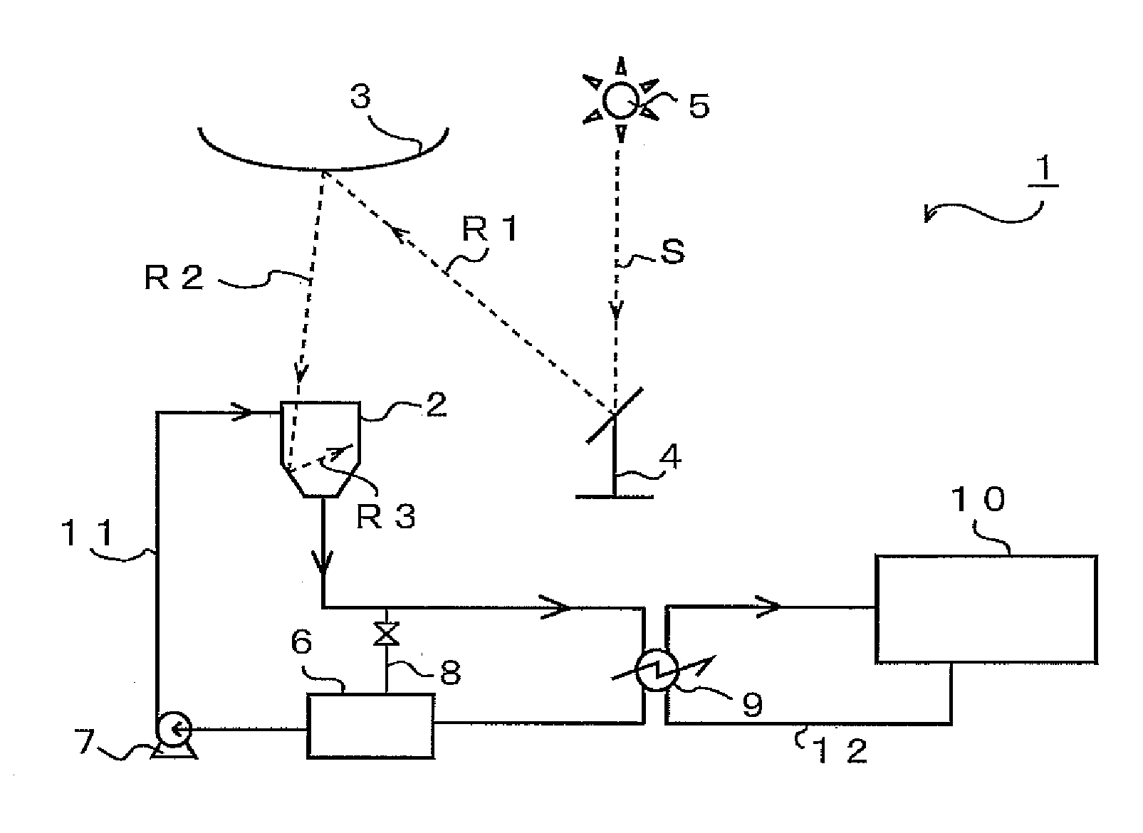
[0039]Hereinbelow, a receiver (heat receiving portion) in a sunlight collecting system according to the present invention and a method of manufacturing the receiver are described with reference to the drawings. FIG. 1 shows a configuration of a beam-down sunlight collecting system 1 according to an embodiment of the present invention. Note that although a beam-down sunlight collecting system is described below, the present invention can be implemented to a central tower sunlight collecting system in which the receiver is installed on an upper portion of a tower-shaped construction, in addition to the beam-down sunlight collecting system.

[0040]First, an overview of the sunlight collecting system 1 is described. The sunlight collecting system 1 is configured as follows. Sunlight S radiated from the sun 5 is reflected by a heliostat (reflection mirror) 4 (reflected light R1), then re-reflected by a center reflector (large reflection mirror) 3 (reflected light R2), and then converged to...


PUM


Abstract

Problem to be Solved
The present invention is made in view of the above-described circumstances. An object of the present invention is to provide a sunlight collecting system achieving suppression of power generation cost with the receiver which enables suppressing the manufacturing, transportation and construction costs, facilitating recovery work in the case of occurrence of a failure, and promptly recovering a heating medium circulating inside the receiver in an emergency.
Means for Solving the Problem
A sunlight collecting system in which sunlight is reflected by a plurality of heliostats onto a heat receiving portion having a heating medium circulated therein and then energy is drawn from the heating medium, characterized in that the sunlight collecting system is configured such that: the heat receiving portion is formed by assembling a plurality of modules, each of the modules includes an upper header, a lower header, and a plurality of heat receiving tubes connecting the two headers, and the heating medium circulates in the modules.

Description

TECHNICAL FIELD[0001]The present invention relates to a sunlight collecting system in which sunlight reflected by multiple heliostats (reflection mirrors) is converged to a receiver (heat receiving portion), and a heating medium circulates in the receiver.BACKGROUND ART[0002]Nowadays, there is a growing concern about depletion and rising cost of oil resources, and studies are conducted on transition to new energy resources from oil resources being one of the reasons for the global warming. One of new energy sources is solar thermal power generation in which sunlight is collected and used as energy.[0003]As the sunlight collecting system, a beam-down sunlight collecting system is known in which sunlight is reflected by heliostats being reflection mirrors toward above a center portion of the system and the reflected light is converged to a receiver (heat receiving portion) installed at a lower portion of the system by a large reflection mirror called a center reflector (see Patent Doc...

Claims


Application Information

Patent Timeline
Patent Type & Authority Applications(United States)
IPC IPC(8): F24J2/24F24J2/26F24S20/30F24S10/70F24S10/75
CPCF24J2/07F24J2/18Y02E10/46Y02E10/41Y02E10/44F24J2/24F24S10/70F24S20/20F24S23/79Y02E10/40
Inventor EZAWA, KAZUAKITSUTSUI, NOBUYUKITOMOYASU, SUMINAO
Owner MITSUI ENG & SHIPBUILD CO LTD
Why Eureka
Try Eureka