

Pneumatic tire
a pneumatic tire and tire body technology, applied in the field of pneumatic tires, can solve the problems of reducing pattern rigidity or increasing groove volume, reducing anti-hydroplaning performance, and reducing anti-slip performance, so as to improve anti-hydroplaning performance, improve anti-slip performance, and prevent degradation of noise performance and steering stability performan
Active Publication Date: 2012-06-28
SUMITOMO RUBBER IND LTD
View PDF10 Cites 27 Cited by
- Summary
- Abstract
- Description
- Claims
- Application Information
AI Technical Summary
Benefits of technology
The technical effect of this patent is to create a pneumatic tire that has better traction against water splashes (anti-hydropaning) without compromising its ability to reduce noise or maintain smooth driving experience. This is achieved through the design of specific patterns on the tire's tread including blocks with center and shoulder circuits, along with improved angles for certain parts. These improvements help ensure optimal grip and control during wet weather conditions.
Problems solved by technology
The technical problem addressed in this patent text relates to improving the anti-hydropaning (also known as prevention of snowplow effect) performance of tires without compromising other important performances like steering stability and noise performance.
Method used
View moreImage
Smart ImageViewing Examples

Examples
 PUM
 Abstract
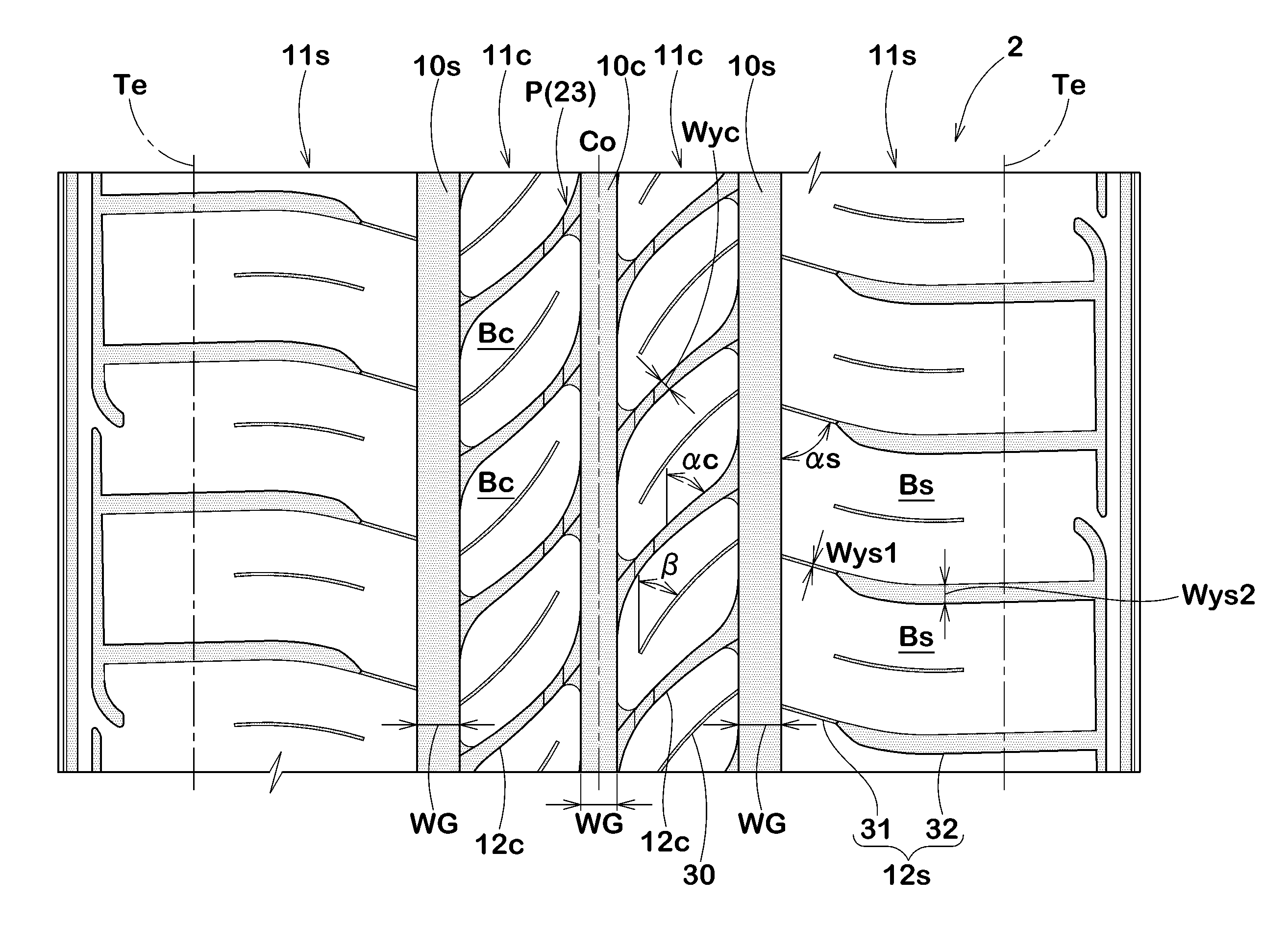
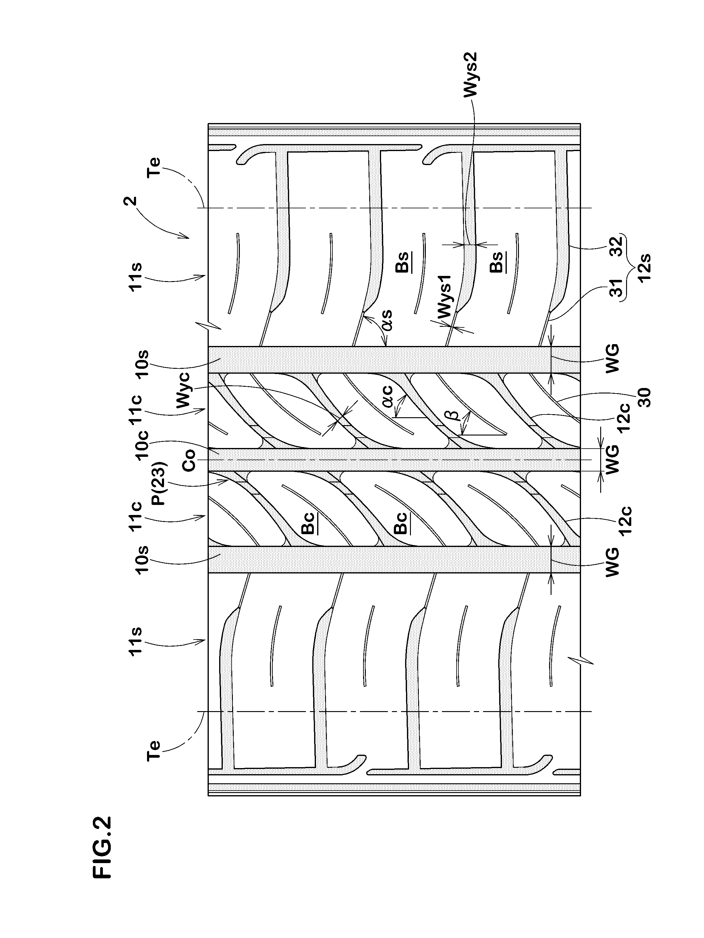
A pneumatic tire tread includes center lateral grooves inclined to the reverse direction of the belt cords of the outermost belt ply of the belt, a groove width Wyc of the center lateral grooves being from 1.0 to 6.0 mm, shoulder lateral grooves being inclined to the same direction of the belt cords of the outermost belt ply, the shoulder lateral grooves having a narrow-width portion having a groove width Wys1 of from 0.4 to 1.5 mm at a position where it connects to a shoulder circumferential main groove, and a wide-width portion having a groove width Wys2 of from 2.0 to 8.0 mm which is connected to the narrow-width portion and extends beyond the tread ground-contact edge.
Description
Login to View More Claims
Login to View More Application Information
Patent Timeline
 OwnerSUMITOMO RUBBER IND LTD