Locking cap for a vessel having a neck

a technology of locking cap and neck, which is applied in the direction of locking device, latching mechanism, closure, etc., can solve the problems of large amount of material and complex mold production, and achieve the effects of easy mounting, easy access to contents, and easy production. , easy to moun

Active Publication Date: 2012-06-28
A RAYMOND & CO
View PDF3 Cites 24 Cited by
  • Summary
  • Abstract
  • Description
  • Claims
  • Application Information

AI Technical Summary

Benefits of technology

[0010]With an arrangement of this kind, the locking cover is easy to mount on the neck of the vessel: once the cage has been introduced into and locked inside the ring and the stopper has then been inserted in the cage and locked in place by means of the second tongues, the cover, with the stopper, is then simply inserted onto the neck by the application of axial pressure un

Problems solved by technology

A disadvantage of this locking cover is that its production by

Method used


Image

  • Locking cap for a vessel having a neck
  • Locking cap for a vessel having a neck
  • Locking cap for a vessel having a neck

Examples


Embodiment Construction

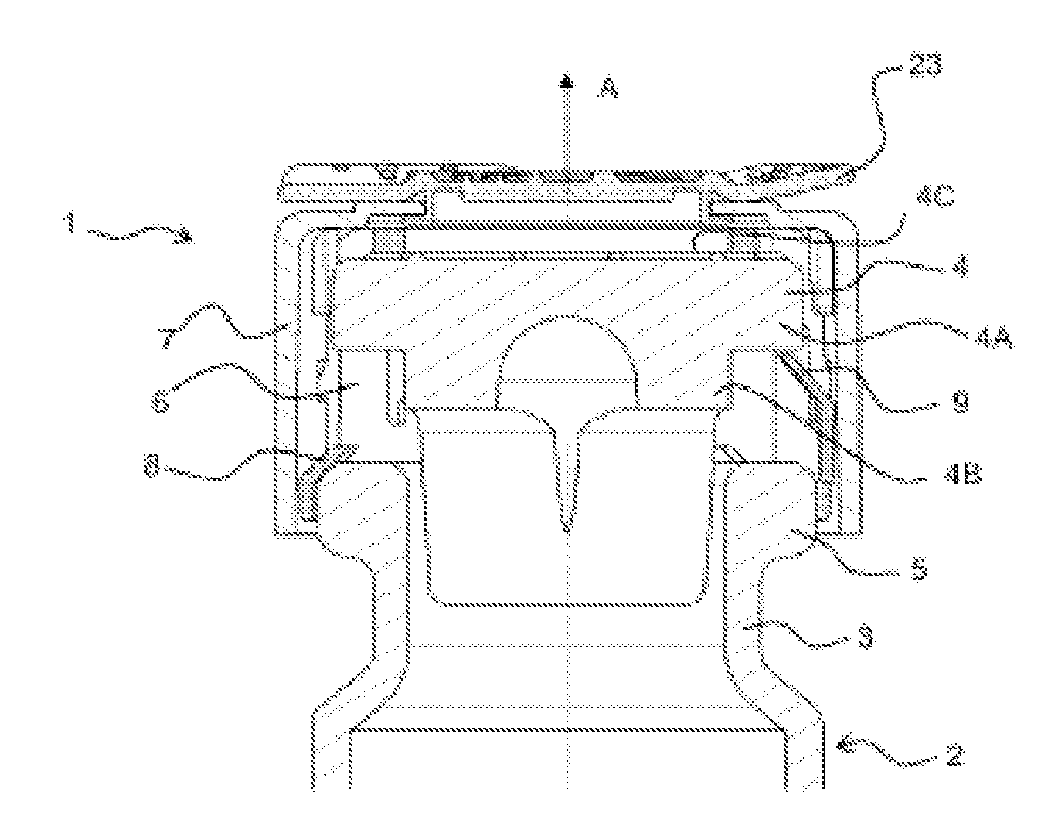
[0027]Represented in FIG. 1 is a locking cover 1 for a vessel 2 having a neck 3 according to the invention, intended to fix a stopper 4 in the neck 3 of the vessel 2, said cover 1 being shown here in a mounted position in which it is merely placed on the neck 3 without being locked.

[0028]The neck 3, which here has a circular opening, has at its end a peripheral outer lip 5 to which the locking cover 1 fixes itself when the cover 1 is locked on the neck 3 of the vessel 2. The stopper 4 here has a conventional, generally cylindrical, “T” shape, with a head 4A and a foot 4B, the head being slightly larger in diameter than the foot 4B, such that when the foot 4B of the stopper 4 is inserted in the neck 3, the head 4A abuts against the lip 5 of the neck 3.

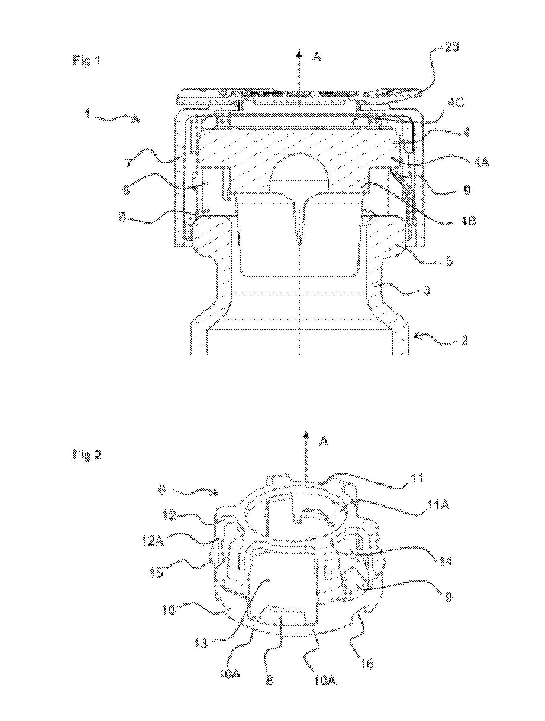
[0029]As can be seen in FIG. 1, the locking cover 1 comprises a cage 6 adapted to surround the stopper 4 and the neck 3, in the locked configuration of the cover 1 on the vessel 2, and a ring 7 adapted to nest over the cage 6, surroundi...


PUM


Abstract

The invention relates to a locking cap (1) made of a molded plastic material for a vessel (2) having a neck, intended for blocking a stopper (4) in said neck (3), including a wire-cap (6) adapted for surrounding the stopper (4) and the neck in the mounted configuration of the cap (1). The wire-cap includes first and second flexible tabs capable of being respectively blocked on the neck and on the stopper (4), said first tabs (8) being offset relative to said second tabs (9) in an axial direction relative to said neck (3). The cap (1) also includes a ring (7) surrounding the wire-cap (6) for preventing access to said tabs from outside the ring (7). The ring (7) and the wire-cap (6) are designed so as to be fitted and locked together. The tabs (8, 9) of the wire-cap are respectively arranged at an angle in first and second openings (13, 14) which are formed by the mesh of the wire-cap (6), and in which the tabs (8, 9) can disappear when mounting the cap (1) on the neck (3).

Description

CROSS-REFERENCE TO RELATED APPLICATION[0001]This application is a U.S. National Phase Patent Application based on International Application Serial No. PCT / EP2010 / 061982 filed Aug. 17, 2010, the disclosure of which is hereby explicitly incorporated by reference herein.BACKGROUND OF THE INVENTION[0002]1. Field of the Invention[0003]The present invention concerns a locking cover made of a molded plastic material for a vessel having a neck.[0004]2. Description of the Related Art[0005]Patent document FR-2893922 discloses a locking cover as described above, in which the cage has a peripheral ring (503A) connected by its bottom edge alternatively to locking tongues of the neck (503G) and to arms (503D) provided with locking tongues for locking onto the stopper. Between the ring and the locking tongues there is a peripheral seat in which is inserted a locking element that pushes the tongues back onto the neck and thus fastens the cover on the neck. This, therefore, constitutes a two-stage l...

Claims


Application Information

Patent Timeline
IPC IPC(8): B65D45/32
CPCB65D55/063B65D51/002B65D45/32B65D55/06
Inventor GELIBERT, STEPHANEBELLE, GUILLAUME
Owner A RAYMOND & CO
Why Eureka
Try Eureka