
Exposure control apparatus for vehicle-mounted camera

a technology of exposure control and camera, which is applied in the direction of color television, television systems, instruments, etc., can solve the problems of lowering recognition accuracy, and inability to perform well exposure control, so as to improve the followability of exposure control

Active Publication Date: 2012-06-28
DENSO CORP
View PDF9 Cites 31 Cited by
  • Summary
  • Abstract
  • Description
  • Claims
  • Application Information

AI Technical Summary

Benefits of technology

The patent describes an exposure control system for a camera on a vehicle that adjusts the camera's exposure based on the brightness of a specific area in the image taken by the camera. The system uses a measuring device to measure the brightness of a landscape area that is farther from the vehicle than the specific area in the image. The system also detects any changes in brightness of the landscape area over time and predicts when the specific area will change in brightness. This allows the camera to be exposed at the predicted time, improving the accuracy of exposure control and ensuring better quality images.

Problems solved by technology

However, since the brightness of the road surface ahead of the vehicle varies depending on various factors such as the light of the headlight of an oncoming vehicle, the shadow of the entrance of a tunnel, and the light at the exit of a tunnel, it may occur that it is impossible to perform the exposure control well following the variation of the brightness.
However, since this method adjusts the exposure after detecting saturation of the signals of a taken image, it has a problem in that the exposure control cannot be performed well following variation of the brightness, and accordingly the recognition accuracy is lowered immediately after the brightness has changed greatly.

Method used


Image

  • Exposure control apparatus for vehicle-mounted camera
  • Exposure control apparatus for vehicle-mounted camera
  • Exposure control apparatus for vehicle-mounted camera

Examples


first embodiment

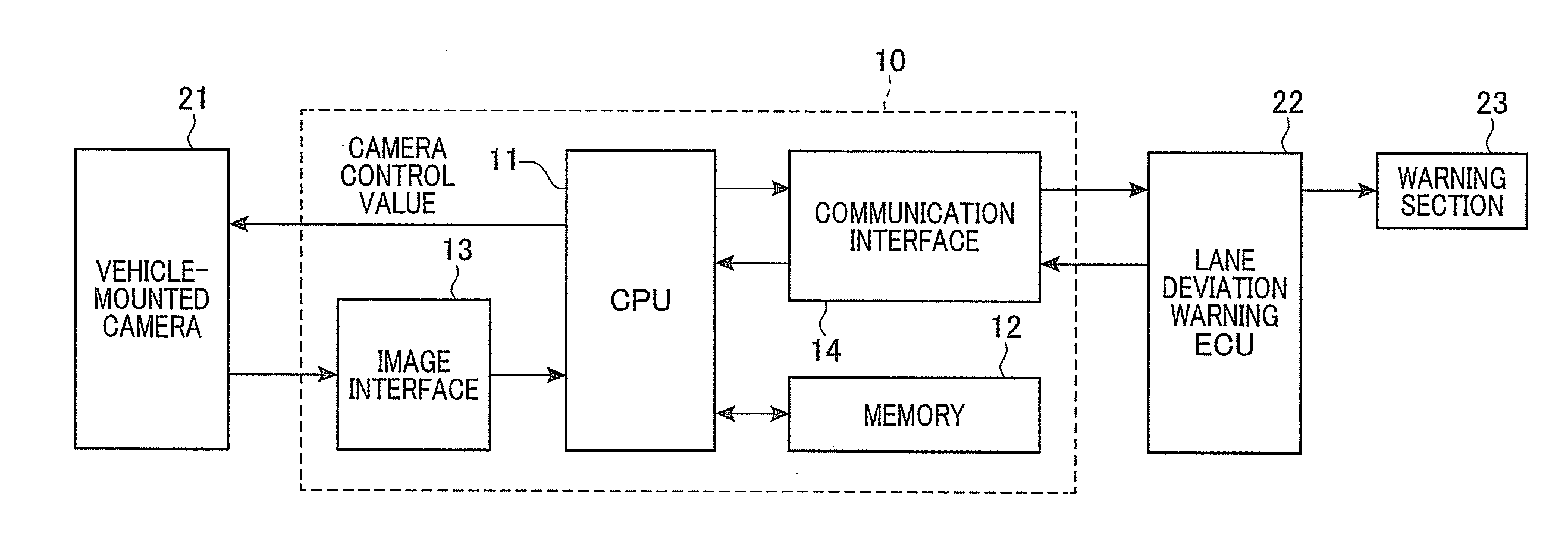
[0029]FIG. 1 is a block diagram showing the structure of an exposure control apparatus 10 according to an embodiment of the invention.

[0030]The exposure control apparatus 10 is mounted on a vehicle together with a vehicle-mounted camera 21, a lane deviation warning ECU 22 and a warning section 23.

[0031]The exposure control apparatus 10 includes a CPU 11, a memory 12, an image interface 13 for receiving images taken by the camera 21 and a communication interface 14 for performing communication with the lane deviation warning ECU 22.

[0032]The camera 21 is located at a position inside the vehicle cabin, which is appropriate for taking an image of the road ahead of the vehicle, for example, on the back of a room mirror. The camera 21 is oriented such that its image area corresponds to a predetermined area ahead of the vehicle.

[0033]The camera 21 includes, in addition to a CCD image sensor or a CMOS sensor, an amplifier and an A / D converter. The amplifier and the A / D converter are for am...


PUM


Abstract

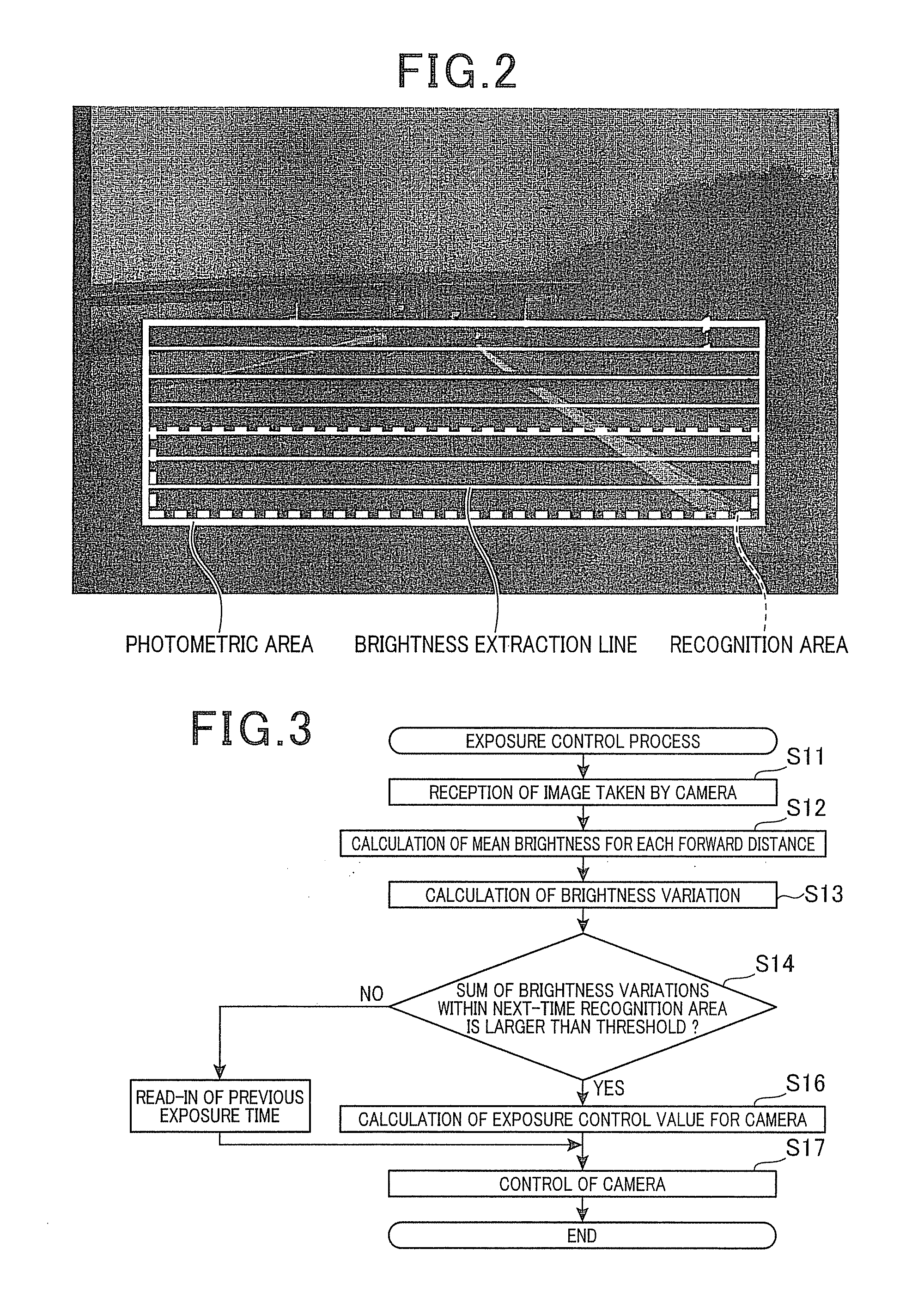
The exposure control apparatus is for performing exposure control for a camera mounted on a vehicle in accordance with brightness of a recognition area set in an image ahead of the vehicle taken by the camera. The exposure control apparatus includes a measuring means for measuring brightness of a photometric area showing a landscape more distant from the vehicle than a landscape shown by the recognition area in each of images successively taken by the camera, a detection means for detecting brightness variation with time of the photometric area based on measurement results by the measuring means for images taken by the camera at different times, and a control means configured to predict a timing at which the brightness of the recognition area changes based on the brightness variation with time of the photometric area, and perform exposure control of the camera at the predicted timing.

Description

[0001]This application claims priority to Japanese Patent Application No. 2010-286290 filed on Dec. 22, 2010, the entire contents of which are hereby incorporated by reference.BACKGROUND OF THE INVENTION[0002]1. Field of the Invention[0003]The present invention relates to an exposure control apparatus used in a vehicle-mounted camera for taking an image ahead of a vehicle.[0004]2. Description of Related Art[0005]There have been proposed various techniques for performing an image processing on images ahead of a vehicle taken by a vehicle-mounted camera to recognize a white line painted on a road or three-dimensional object such as a preceding vehicle, to thereby issue a warning, or perform vehicle running control based on the recognition results. To increase the accuracy of recognition of a white line or a three-dimensional object, it is a matter of great importance to properly perform exposure control of the vehicle-mounted camera in accordance with brightness of an area ahead of th...

Claims


Application Information

Patent Timeline
Patent Type & Authority Applications(United States)
IPC IPC(8): H04N7/18G06V10/22
CPCG06K9/2054G06K9/00798H04N5/2351G06V20/588G06V10/22H04N23/71
Inventor MURAO, TOSHIKAZUKIMURA, TAKAYUKI
Owner DENSO CORP
Learn More