Wireless charging transmitter for portable electronic device
a wireless charging and electronic device technology, applied in electric power, electric vehicles, transportation and packaging, etc., can solve the problems of connecting wires becoming obstacles to charging chargers, portable electronic devices failing to connect to power sources at any time,
- Summary
- Abstract
- Description
- Claims
- Application Information
AI Technical Summary
Problems solved by technology
Method used
Image

Examples
first embodiment
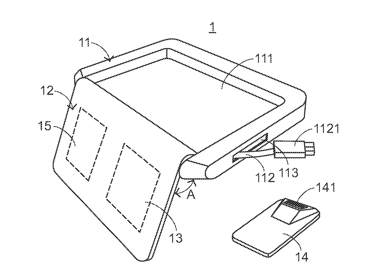
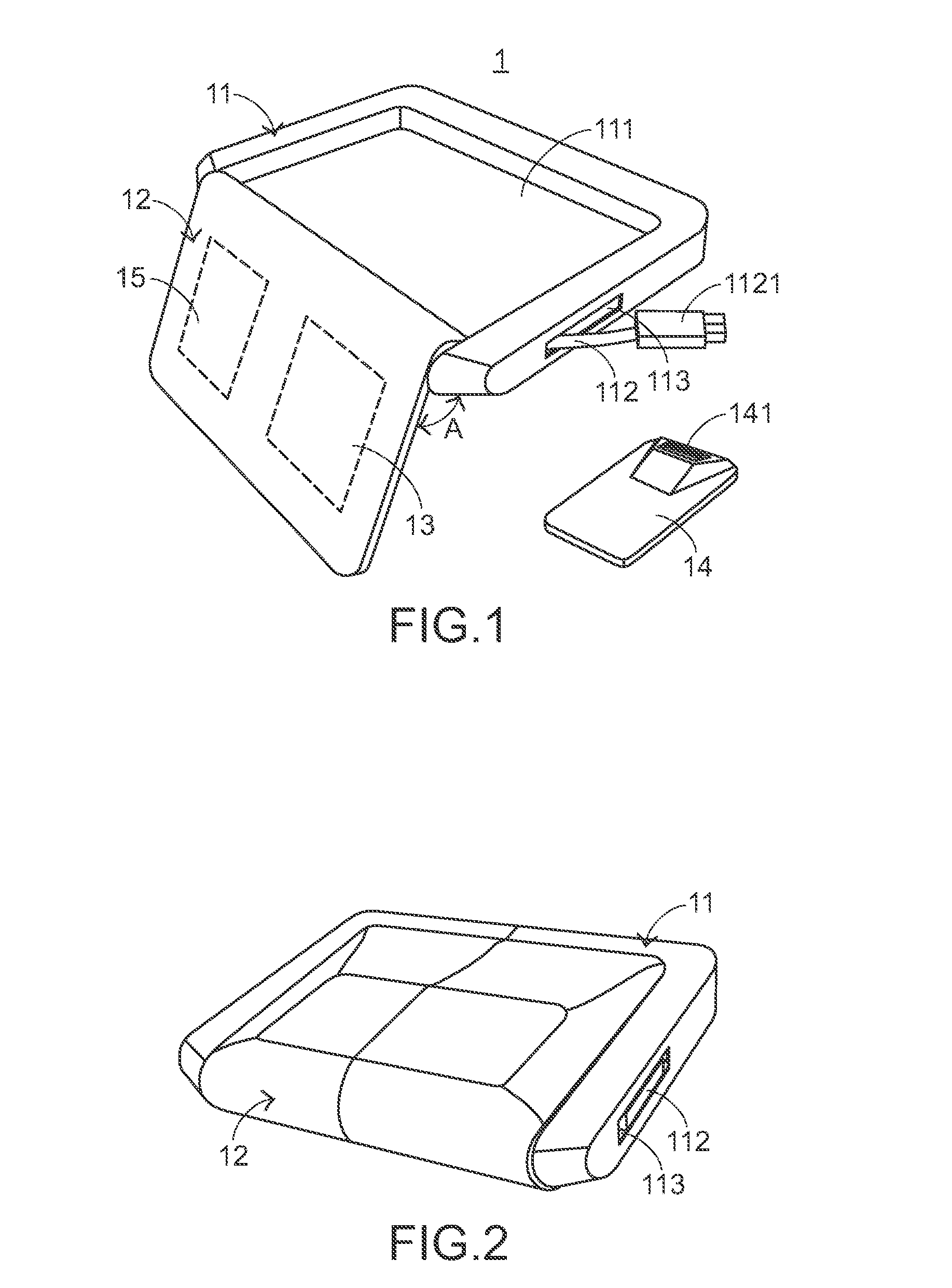
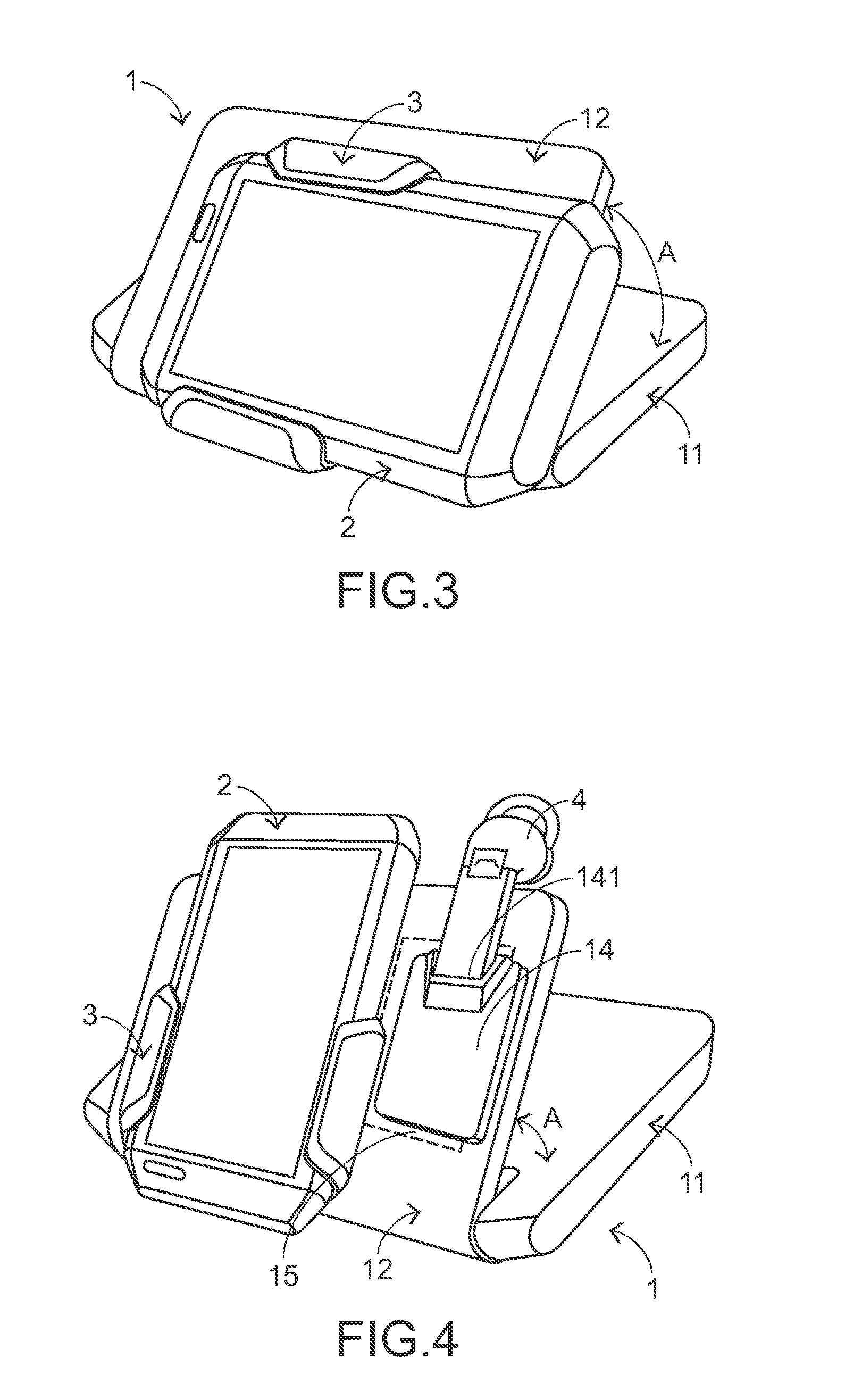
[0035]FIG. 1 is a schematic perspective view illustrating a wireless charging transmitter for a portable electronic device according to the present invention, in which the wireless charging transmitter is in an unfolded status. As shown in FIG. 1, the wireless charging transmitter 1 comprises a first housing 11, a second housing 12, a first wireless charge transmitting module 13, a wireless charge receiving seat 14 and a second wireless charge transmitting module 15. The first housing 11 comprises a receptacle 111, a connecting wire 112 and a wire-receiving part 113. The wireless charge receiving seat 14 may be selectively accommodated within the receptacle 111. After the connecting wire 112 is connected with a power source (not shown), the electric power from the power source may be transmitted to the first wireless charge transmitting module 13 and the second wireless charge transmitting module 15 through the connecting wire 112. In addition, a connector 1121 is formed on a termin...
second embodiment
[0043]Hereinafter, the use of the wireless charging transmitter 5 to transmit electric power to the portable electronic device 2 will be illustrated with reference to FIG. 7. FIG. 7 is a schematic perspective view illustrating a system of transmitting electric power to the wireless charging receiver and the wirelessly-chargeable electronic device through the wireless charging transmitter according to the present invention. For wirelessly charging the portable electronic device 2, the second housing 52 is rotated with respect to the first housing 51 until the second housing 52 is parallel with the first housing 51. Meanwhile, the included angle A′ between the second housing 52 and the first housing 51 is equal to 180 degrees. In this situation, the wireless charging transmitter 5 is substantially a flat slab. Then, the wireless charging receiver 3 holding the portable electronic device 2 is contacted with the second housing 12. That is, the wireless charging receiver 3 is placed on t...
third embodiment
[0047]FIG. 9 is a schematic perspective view illustrating a wireless charging transmitter for a portable electronic device according to the present invention. As shown in FIG. 9, the wireless charging transmitter 6 comprises a first housing 61, a second housing 62, a first wireless charge transmitting module 63 and a second wireless charge transmitting module 64. The first housing 61 has an insertion slot 611, which is formed in a sidewall of the first housing 61. When a terminal of a wirelessly-chargeable electronic device 4″ is inserted into the insertion slot 611, the wirelessly-chargeable electronic device 4″ is fixed in the insertion slot 611. In this embodiment, the wirelessly-chargeable electronic device 4″ is a wireless headset. The second housing 62 has a surface 621 and a receptacle 622. The receptacle 622 is formed in the surface 621 of the second housing 62. The first wireless charge transmitting module 63 is installed within the second housing 62. In a case that a wirel...
PUM
 Abstract
Description
Claims
Application Information
 - Generate Ideas
- Intellectual Property
- Life Sciences
- Materials
- Tech Scout
- Unparalleled Data Quality
- Higher Quality Content
- 60% Fewer Hallucinations
Browse by: Latest US Patents, China's latest patents, Technical Efficacy Thesaurus, Application Domain, Technology Topic, Popular Technical Reports.
© 2025 PatSnap. All rights reserved.Legal|Privacy policy|Modern Slavery Act Transparency Statement|Sitemap|About US| Contact US: help@patsnap.com