Retrofit system for tethering a hand tool

Active Publication Date: 2012-07-12
PURE SAFETY GRP INC
View PDF12 Cites 8 Cited by
  • Summary
  • Abstract
  • Description
  • Claims
  • Application Information

AI Technical Summary

Benefits of technology

[0010]It is an object of the present invention to provide a retrofit system for tethering a tool. It is another object of the present invention to provide a retrofit system for tethering a tool that allows for the full intended use of the tool. It is a further object of the present invention to provide a retrofit system for tethering a tool that minimizes the entanglement of the tool lanyard with the tool during use.
[0011]The present invention achieves these and other objectives by providing a retrofit system that includes a tool collar and a tethering tab. In one embodiment, the tool collar has a collar body, a first body end, a second body end, and a bore extending longitudinally therethrough and a tethering tab having a first tab opening and a second tab opening where the tab openings are transverse to the longitudinal axis of the tethering tab. The bore has a cross-sectional area that is less than the cross-sectional area of a first tool portion of the hand tool providing a snug fit of the tool collar on the first tool portion. The second tab opening of the tethering tab is spaced from the first tab opening where the first tab opening has a cross-sectional area larger than the cross-sectional area of the first tool portion providing for free rotation of the tethering tab around the first tool portion.

Problems solved by technology

There are disadvantages to these tubular retrofit systems.
For example, when used on screw drivers, the eyelet interferes with the full usefulness of the tool.
If the eyelet is at the end of the tool, this cannot be accomplished successfully.
For tubular devices relying on the suction caused by insertion of the tool into the tubular, flexible material, another disadvantage arises.
This abrupt release causes the tool to quickly release with accelerating force due to the amount of force required to pull the screw driver or other tool necessary to counter the suction force created when applying the tubular device to the tool.
If a tool has a sharp end such as most screw drivers, the user / worker and / or bystander could be injured.

Method used


Image

  • Retrofit system for tethering a hand tool
  • Retrofit system for tethering a hand tool
  • Retrofit system for tethering a hand tool

Examples


Embodiment Construction

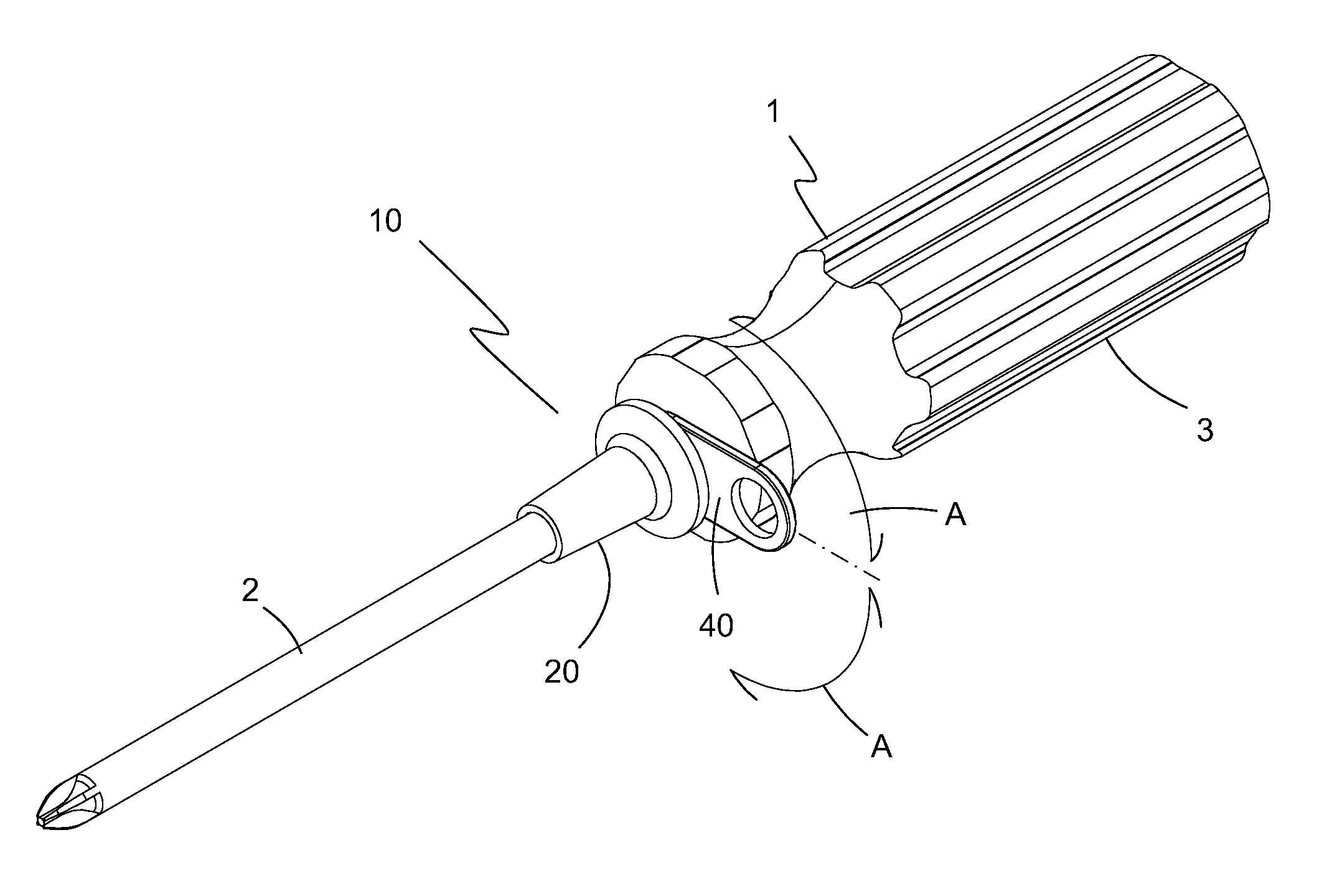
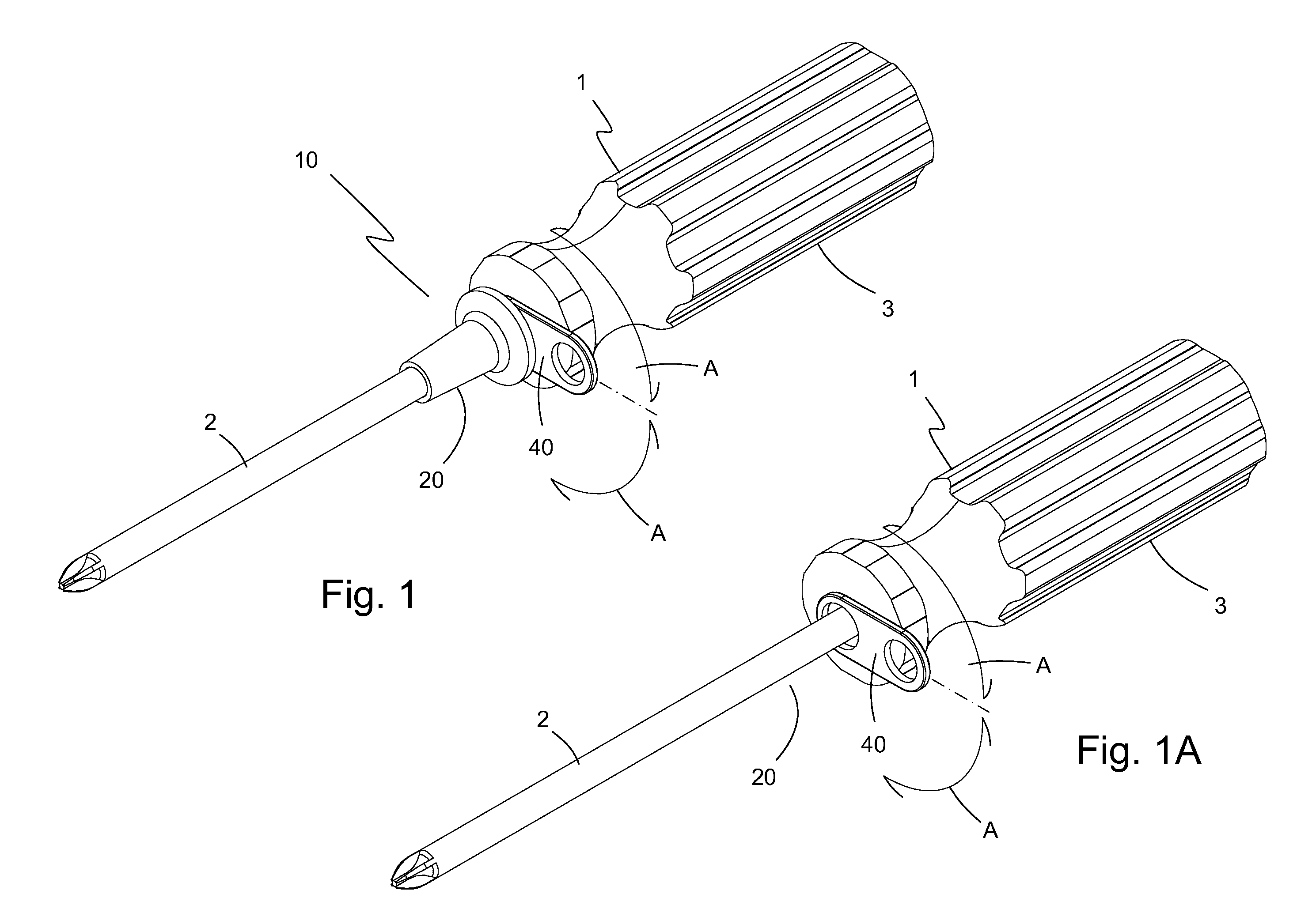
[0032]The preferred embodiment(s) of the present invention is illustrated in FIGS. 1-10. FIG. 1 illustrates one embodiment of a retrofit system 10 of the present invention connected to a hand tool 1. Retrofit system 10 includes a tool collar 20 and a tethering tab 40. As illustrated, tethering tab 40 is mounted on a first tool portion 2 adjacent a second tool portion 3 of hand tool 1. In FIG. 1, hand tool 1 is represented by a screw driver. Tethering tab 40 freely rotates around first tool portion 2, which is indicated by arrows A. FIG. 1A shows tethering tab 40 without tool collar 20 on hand tool 1 to more clearly show the rotational relationship between tethering tab 40 and first tool portion 2. When a lanyard / tether (not shown) is connected to tethering tab 40, the free rotation of tethering tab 40 around first tool portion 2 does not interfere with the use of hand tool 1. The freely rotating tethering tab 40 permits rotation of hand tool 1 when inserting or removing a screw fast...


PUM

PropertyMeasurementUnit
Lengthaaaaaaaaaa
Thicknessaaaaaaaaaa
Diameteraaaaaaaaaa

Abstract

A retrofit system for tethering a hand tool includes a tool collar having a collar body, a first body end, a second body end, and a bore extending longitudinally therethrough, and a tethering tab having a first tab opening and a second tab opening transverse to the longitudinal axis of the tethering tab. The bore of the tool collar has a cross-sectional area that is less than the cross-sectional area of a first tool portion of the hand tool providing a snug fit of the tool collar on the first tool portion. The second tab opening of the tethering tab being spaced from the first tab opening and the first tab opening having a cross-sectional area larger than the cross-sectional area of the first tool portion providing for free rotation of the tethering tab around the first tool portion.

Description

BACKGROUND OF THE INVENTION[0001]1. Field of the Invention[0002]The present invention relates generally to hand tools. Particularly, the present invention relates to hand tools and tethering of the same.[0003]2. Description of the Prior Art[0004]It is a generally accepted safety practice to secure a workman's tools in some manner when working from a ladder or above ground level. Over the years different types of devices for preventing the accidental dropping and / or loss of a tool and a tool accessory have been attempted when working in overhead situations. A dropped tool or tool accessory could be hazardous for personnel working below or the dropped tool or tool accessory could potentially damage a vital piece of equipment. This can occur when the tool is mishandled, bumped, or jarred, becoming dislodged from the users hand and free to fall to whatever is beneath the worker. In some cases, this can be a passerby, another worker or even vital plant equipment.[0005]Typically, the tool...

Claims


Application Information

Patent Timeline
IPC IPC(8): A45F5/00B23P23/00
CPCY10T24/13B25B15/02B25B7/00Y10T29/49716
Inventor MOREAU, DARRELL A.MOREAU, ANDRE W.
Owner PURE SAFETY GRP INC
Why Eureka
Try Eureka