Wind powered cooling system

a cooling system and wind power technology, applied in the field of wind power cooling systems, can solve the problems of large amount of carbon dioxide emissions, large energy consumption of such systems, and occupants' discomfort, and achieve the effect of reducing the entanglement of conduits

Pending Publication Date: 2021-12-23
BASKAR JAGANNATHAN
View PDF2 Cites 0 Cited by
  • Summary
  • Abstract
  • Description
  • Claims
  • Application Information

AI Technical Summary

Benefits of technology

[0024]Preferably, the passive yaw system allows rotation of the conduits associated with the rotating parts of the system so as to minimize entanglement of the conduits.
[0034]the rotating section is configured to rotate with the frame about the yaw axis,wherein the transmission is mechanically couplable to a compressor, the compressor including a first member for translating the rotational energy of the transmission to movement of the first member with respect to a second member so as to compress a refrigerant fluid stored therein, andthe compressor being in fluid communication with an evaporator for expanding and evaporating compressed refrigerant fluid into cold refrigerant gas so as to cool air surrounding the evaporator system by convection.

Problems solved by technology

In countries where the temperature is hot, indoor air temperatures are often high resulting in occupants feeling uncomfortable.
An issue arising from this increase in heating, ventilation and air conditioning (HVAC) systems is the energy required to power such systems is quite high.
This results in a vast amount of carbon dioxide emissions which may contribute to global warming.
However, current systems that are powered by renewal energy typically require higher cost compared to a traditional system to buy, install, operate and maintain the system.
Additionally, in some countries, access to clean potable water can be limited.
This can result in a lack of drinking water and the inability to grow crops due to insufficient irrigation.

Method used


Image

  • Wind powered cooling system
  • Wind powered cooling system
  • Wind powered cooling system

Examples


Embodiment Construction

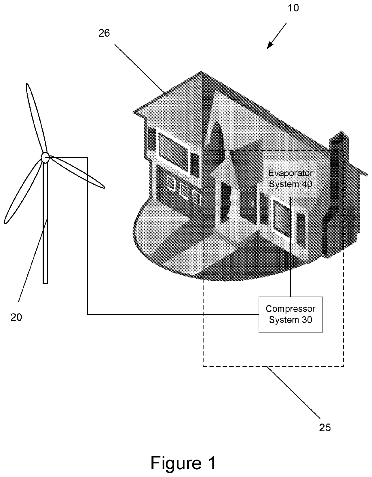
[0049]The system 10 shown in FIG. 1 is for cooling air powered by the wind's kinetic energy. The system 10 can be used to cool indoor spaces 26 or outdoor spaces such as the adjacent space around the exterior of a residential home or a beach side resort.

[0050]Additionally, when used in humid climate conditions, the system 10 can be used to produce potable water obtained from condensation of the air's moisture. For example, the potable water from system 10 can be used as an alternate source of water in developing countries with a lack of access to clean potable water. The potable water can also be used for farming in arid regions and raising crops which are not water intensive.

[0051]The system 10 can also used as an alternative to convention cooling devices like air conditioners or dehumidifiers which are powered by fossil fuels. Advantageously, the system 10 provides lower operational costs compared to conventional systems which may result in high utility bills.

[0052]As particularly...


PUM


Abstract

A wind powered cooling system, including a windmill including a transmission rotatably coupled to at least one vane, wherein wind moving past the vane causes the vane to rotate and transmit rotational energy to the transmission; and a cooling system including: a compressor system including a compressor mechanically coupled to the transmission, the compressor including a first member for translating rotational energy of the transmission to movement of the first member with respect to a second member so as to compress a refrigerant fluid stored therein; and an evaporator system including an evaporator in fluid communication with the compressor for expanding and evaporating compressed refrigerant fluid into cold refrigerant gas, wherein the cold refrigerant gas cools air surrounding the evaporator system by convection.

Description

FIELD OF THE INVENTION[0001]The present invention relates to a wind powered cooling system. The present invention also relates to an apparatus for harnessing wind energy to cool air. The present invention also relates to a wind powered clean water generating system.BACKGROUND OF THE INVENTION[0002]In countries where the temperature is hot, indoor air temperatures are often high resulting in occupants feeling uncomfortable. Thermal comfort is usually achieved when the temperature and relative humidity surrounding an occupant is within a certain range, for example 23° C. to 25° C. is ideal comfort temperature range. This range may change depending on the relative temperature outdoors and the occupant's expectation.[0003]Operating a device to regulate the indoor temperature of a space requires some form of energy input. This energy input may become quite substantial depending on the efficiency of the cooling system and the amount of heat required to be removed from a space, for example...

Claims


Application Information

Patent Timeline
Patent Type & Authority Applications(United States)
IPC IPC(8): F24F5/00F25D21/14F25B27/00F25B40/04F03D9/20F03D15/00
CPCF24F5/0046F25D21/14F25B27/00F05B2260/20F03D9/20F03D15/00F25B2339/046F25B40/04F05B2240/9112F03D9/22F25B1/04F25B5/02F25B2400/05F25B2600/2507F25B49/02F25B2700/2104F25B40/00Y02E10/728Y02B10/30Y02E10/72Y02E70/30
Inventor BASKAR, JAGANNATHAN
Owner BASKAR JAGANNATHAN
Why Eureka
Try Eureka