
System and method for controlling a gas turbine engine afterburner

Inactive Publication Date: 2012-07-12
HONEYWELL INT INC
View PDF3 Cites 6 Cited by
  • Summary
  • Abstract
  • Description
  • Claims
  • Application Information

AI Technical Summary

Benefits of technology

[0043]It is noted that if the software switch 726 is positioned such that the equivalent steady state throttle position (PCT_SS) is passed directly to the subtraction summing function 728, then thrust modulation of the afterburner 144 will track engine speed. This has the advantage of providing relatively smooth afterburner thrust modulation because engine speed cannot change very fast due to inertia. However, it also exhibits some disadvantages. First, it could produce relatively sluggish and non-synchronized afterburner thrust response because afterburner thrust generation may be slowed down by various control loop dynami

Problems solved by technology

This is because afterburner fuel efficiency is usually relatively poor as compared to the main engine.
Unfortunately, activating and deactivating the afterburner during landing or combat maneuvers can create a thrust discontinuity due to a delay in afterburner activation and a subsequent thrust jump.
As a result, the pilot may not be able to smoothly and precisely modulate thrust during such maneuvers.
During a landing maneuver, this can undesirably cause the aircraft to drift off of the glide slope.
This can cause the pilot to have to make numerous and instant adjustments to the throttle position during landing, which can be both physically and mentally taxing.

Method used


Image

  • System and method for controlling a gas turbine engine afterburner
  • System and method for controlling a gas turbine engine afterburner
  • System and method for controlling a gas turbine engine afterburner

Examples


Embodiment Construction

[0020]The following detailed description is merely exemplary in nature and is not intended to limit the invention or the application and uses of the invention. As used herein, the word “exemplary” means “serving as an example, instance, or illustration.” Thus, any embodiment described herein as “exemplary” is not necessarily to be construed as preferred or advantageous over other embodiments. All of the embodiments described herein are exemplary embodiments provided to enable persons skilled in the art to make or use the invention and not to limit the scope of the invention which is defined by the claims. Furthermore, there is no intention to be bound by any expressed or implied theory presented in the preceding technical field, background, brief summary, or the following detailed description.

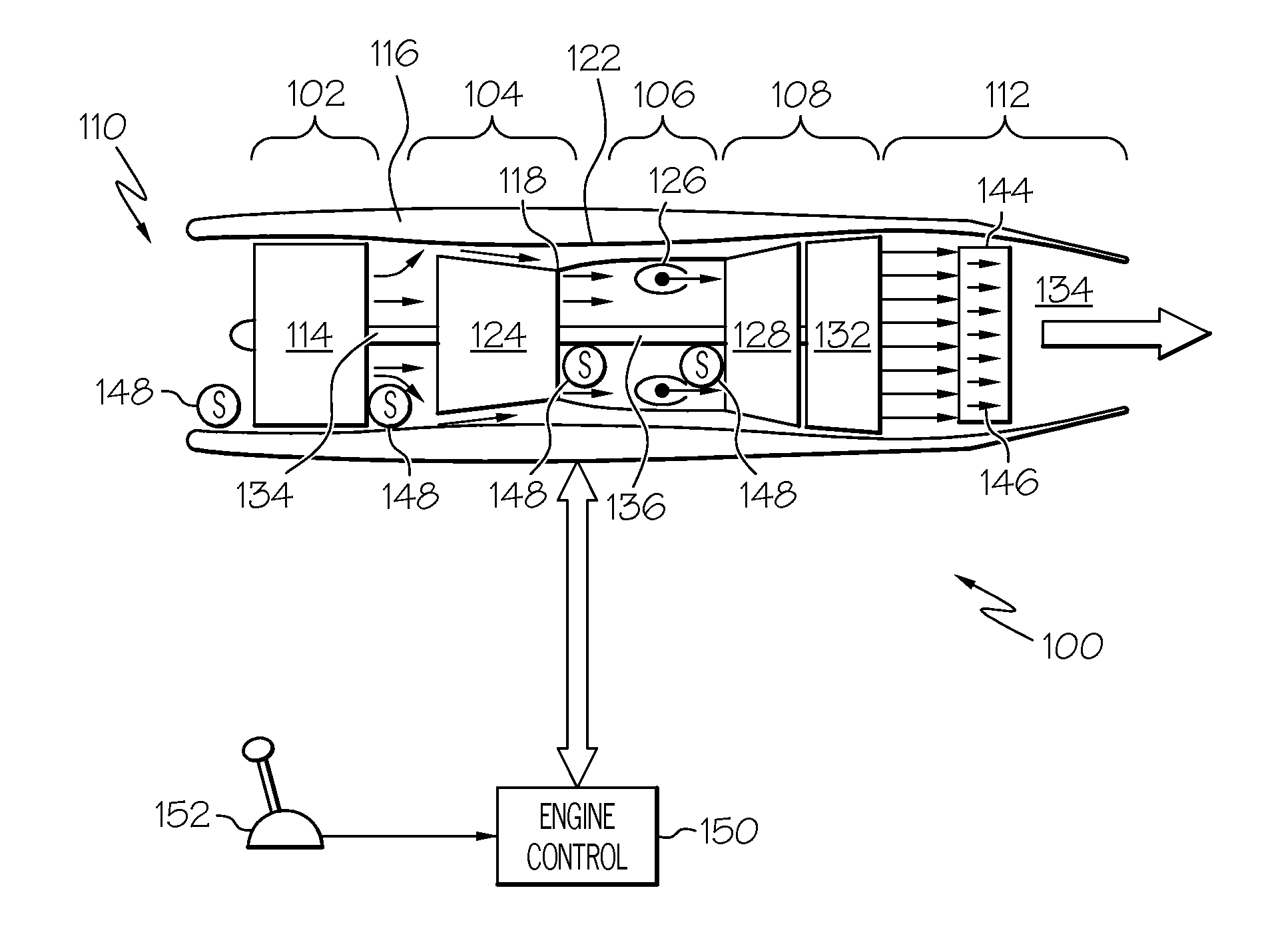
[0021]Turning now to FIG. 1, a functional block diagram of an exemplary gas turbine engine control system 100 is depicted. The depicted engine control system 100 includes a gas turbine engine 1...


PUM


Abstract

Methods and apparatus are provided for operating a gas turbine engine. In a first operational mode, the gas turbine engine generates thrust using the propulsion turbine and not the afterburner when it is commanded to generate a thrust between at least a first thrust magnitude and a second thrust magnitude, and generates thrust using the propulsion turbine and the afterburner when it is commanded to generate thrust greater than the second thrust magnitude. In a second operational mode, the gas turbine engine generates thrust using the propulsion turbine and the afterburner when it is commanded to generate a thrust greater than the first thrust magnitude. The steady state thrust-versus-throttle position response has a substantially constant linear slope that is set to be two times the similar slope of the first operational mode. Thrust transients of the propulsion turbine and the afterburner are substantially synchronizing when the gas turbine engine is operating in the second mode and generating thrust greater than first thrust magnitude.

Description

TECHNICAL FIELD[0001]The present invention generally relates to gas turbine engine control, and more particularly relates to systems and methods for controlling a gas turbine engine afterburner.BACKGROUND[0002]Some aircraft gas turbine propulsion engines are equipped with an afterburner. An afterburner (or reheat) is typically disposed downstream of the turbine and upstream of the exhaust nozzle, and includes a plurality of fuel injectors. The afterburner provides increased thrust by injecting fuel, via the fuel injectors, into the exhaust section of the engine downstream of the turbine. An afterburner may be used to provide increased thrust for supersonic flight, for takeoff and, in the case of military aircraft, for combat situations. No matter the reason for its specific use, an afterburner in an aircraft gas turbine propulsion engine is typically activated only after the propulsion turbine has reached its maximum speed and thrust. This is because afterburner fuel efficiency is u...

Claims


Application Information

Patent Timeline
IPC IPC(8): F02K3/10
CPCF02C9/16F02C9/26F02K3/10F02K1/16F02K1/17F02C9/48F02C9/28F02C9/285
Inventor LING, RICHARDKEPPLER, KARLSHEPHERD, KEVINDENTON, MARK LEE
Owner HONEYWELL INT INC
Learn More