
Ball roller bearing

a ball roller bearing and roller bearing technology, applied in the direction of roller bearings, bearings, engine components, etc., can solve the problems of ball rollers jamming in the cage pocket of the cage, the bearing cage does not meet the specified quality requirements, and the ball roller bearing malfunctions, etc., to achieve cost-neutral

Inactive Publication Date: 2012-07-12
SCHAEFFLER TECH AG & CO KG
View PDF0 Cites 3 Cited by
  • Summary
  • Abstract
  • Description
  • Claims
  • Application Information

AI Technical Summary

Benefits of technology

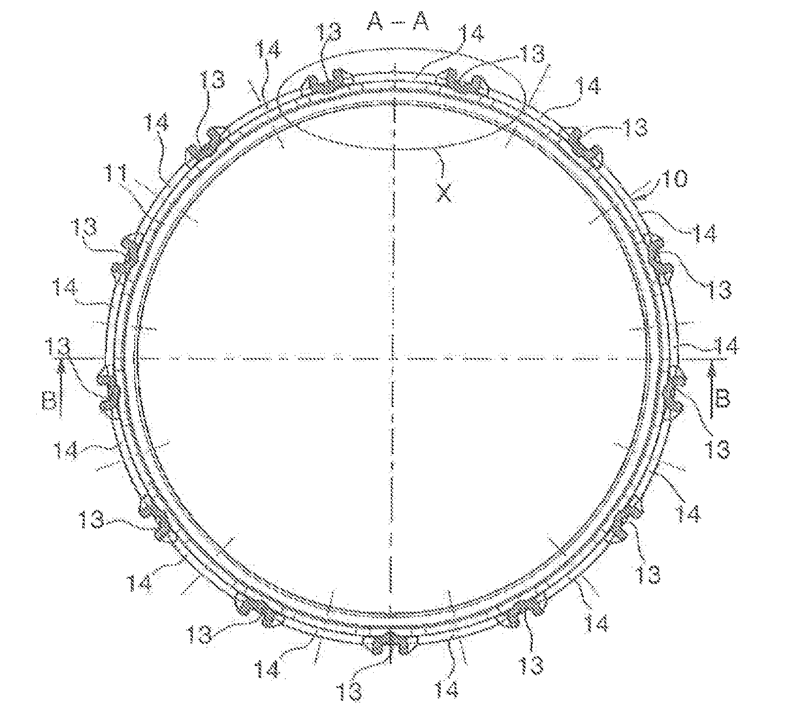
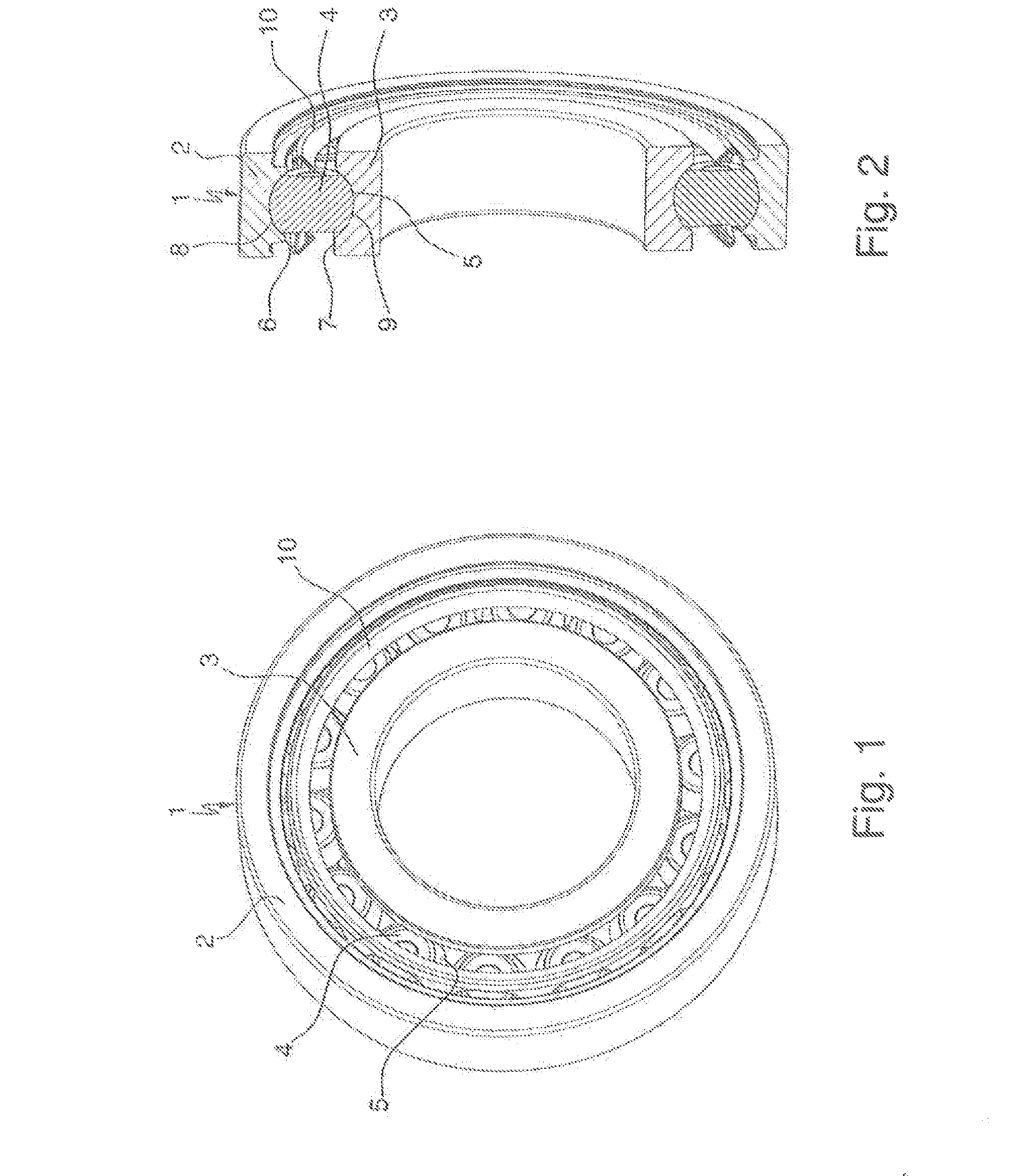
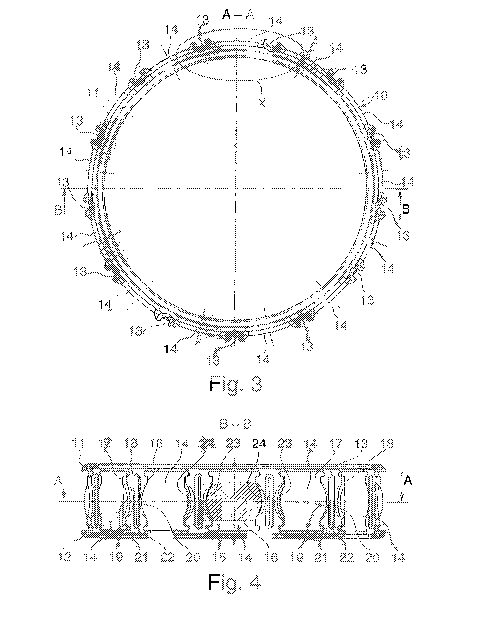
[0007]According to the invention, this object is achieved, in the case of a ball roller bearing in accordance with the preamble of claim 1, in that the pocket webs have additional material profiles for axial reinforcement of the bearing cage, both between their side edges and on their guide faces, and the material profiles on their guide faces are configured at the same time as damping means against bearing noise.
[0008]Here, the invention is based on the finding that, as a result of targeted material profiles on the pocket webs of the bearing cage, a pocket geometry can be provided which firstly brings about a considerable axial reinforcement of the bearing cage and therefore avoids the axial bulges of the pocket webs, which axial bulges are produced during the concluding flanging of the lateral angular flanges, and which at the same time chamfers the sharp-edged guide faces on the cage pockets and therefore avoids undesirable bearing noise.
[0011]Moreover, it is also a second advantageous refinement of the ball roller bearing which is configured according to the invention according to claim 3 that the material profiles on the guide faces of the pocket webs are preferably configured as radially outwardly directed borders of material tabs which are additionally formed integrally onto the guide faces. Here, said material tabs are likewise produced with the punching of the cage pockets out of the sheet metal strip and are therefore likewise virtually cost-neutral. Here, the borders produced with said material tabs on the guide faces of the cage pockets contribute to the further axial reinforcement of the pocket webs of the hearing cage and at the same time have the further advantage that, as a result of the produced rigidity and as a result of the rounded profile of the guide faces which is produced, they act as damping means against the bearing noise produced during bearing operation during the forward and backward running of the ball rollers.

Problems solved by technology

It has been found in practice, however, that the production of the bearing cage in the form described is subject to special technical problems, and furthermore the function of the bearing cage does not fully meet the specified requirements in terms of quality.
As a result, during the flanging of the lateral angular flanges which concludes the hearing assembly, axial bulges of the pocket webs occur, which bulges can lead to the ball rollers jamming in their cage pockets and ultimately to malfunctions of the ball roller bearing.
The low flexural stiffness of the pocket webs can likewise lead to high fluctuations in the cage deflection during hearing operation, as a result of which undesirable high bearing noise additionally occurs in conjunction with the sharp edges of the punched-out cage pockets.

Method used


Image

  • Ball roller bearing
  • Ball roller bearing
  • Ball roller bearing

Examples


Embodiment Construction

[0007]According to the invention, this object is achieved, in the case of a ball roller bearing in accordance with the preamble of claim 1, in that the pocket webs have additional material profiles for axial reinforcement of the bearing cage, both between their side edges and on their guide faces, and the material profiles on their guide faces are configured at the same time as damping means against bearing noise.

[0008]Here, the invention is based on the finding that, as a result of targeted material profiles on the pocket webs of the bearing cage, a pocket geometry can be provided which firstly brings about a considerable axial reinforcement of the bearing cage and therefore avoids the axial bulges of the pocket webs, which axial bulges are produced during the concluding flanging of the lateral angular flanges, and which at the same time chamfers the sharp-edged guide faces on the cage pockets and therefore avoids undesirable bearing noise.

[0009]Preferred embodiments and / or develop...


PUM


Abstract

A ball roller bearing which has an outer and inner bearing ring and ball rollers arranged between the rings, which roll in two groove-shaped tracks in the rings and are held at a uniform distance to one another by a window cage. The cage has two lateral angle ribs, pocket bridges, which connect the ribs and cage pockets separated by the pocket bridges. The pockets have a cross-shaped hole formed from a contour perpendicular to the circumferential direction and a cross-sectional contour of a ball roller arranged longitudinally to the circumferential direction. The side edges are formed from the pocket bridges, which have radii of arch-shaped guide surfaces corresponding to the running surfaces of two ball rollers. The pocket bridges have additional material profiling between the side edges and on the guide surfaces for axial stiffening of the cage and damping bearing noise.

Description

FIELD OF THE INVENTION[0001]The invention relates to a single-row ball roller bearing in accordance with the features that form the preamble of patent claim 1, which can be used to particular advantage as a fixed bearing for the input or output shaft of a motor vehicle shift transmission, for example.BACKGROUND OF THE INVENTION[0002]Ball roller bearings are rolling contact bearings with special roiling elements designed as ball rollers, which, starting from a basic ball shape, each have two side faces, which are formed as flats on said basic ball shape, which are arranged parallel to one another and between which the running surfaces of the ball rollers are in each case arranged. Ball roller bearings of this kind are widely known in many different versions in the form of single-, two-, three- or even four-row radial or angular contact ball roller bearings and, owing to the special shape of the rolling elements, they also require special cage designs in order, on the one hand, to lim...

Claims


Application Information

Patent Timeline
Patent Type & Authority Applications(United States)
IPC IPC(8): F16C33/38
CPCF16C19/26F16C33/36F16C2361/61F16C33/545F16C33/467F16C2361/65
Inventor HOFMANN, HEINRICHBOHR, ANDREAS-JOHANNGEIGER, ERNSTWEBER, OTMAR
Owner SCHAEFFLER TECH AG & CO KG
Learn More