
Ball roller bearing
a ball roller bearing and roller bearing technology, applied in the direction of roller bearings, bearings, engine components, etc., can solve the problems of ball rollers jamming in the cage pocket of the cage, ball roller bearing malfunction, bearing cage not fully meeting the specified requirements in terms of quality, etc., to avoid undesirable bearing noise and cost-neutral
- Summary
- Abstract
- Description
- Claims
- Application Information
AI Technical Summary
Benefits of technology
Problems solved by technology
Method used
Image

Examples
Embodiment Construction
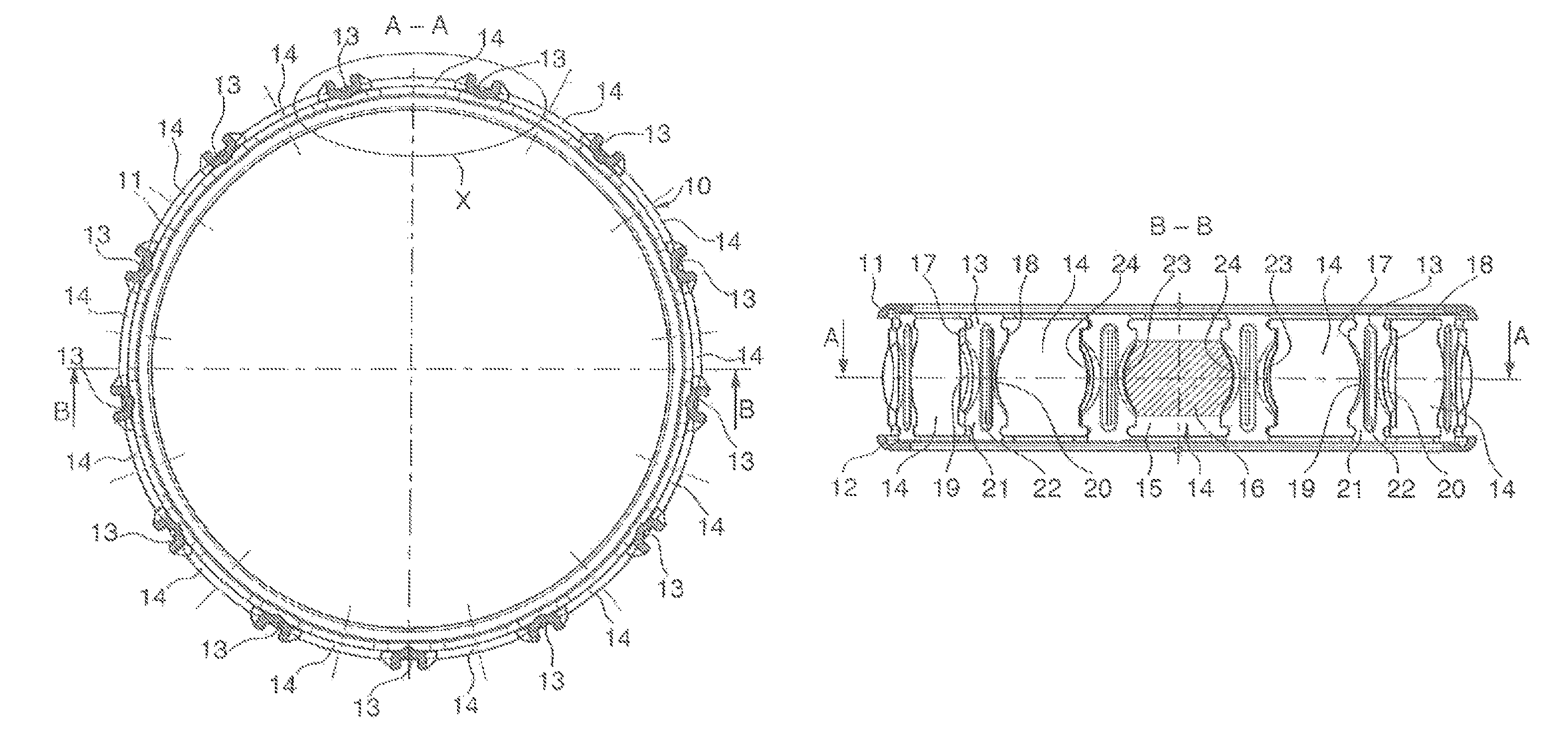
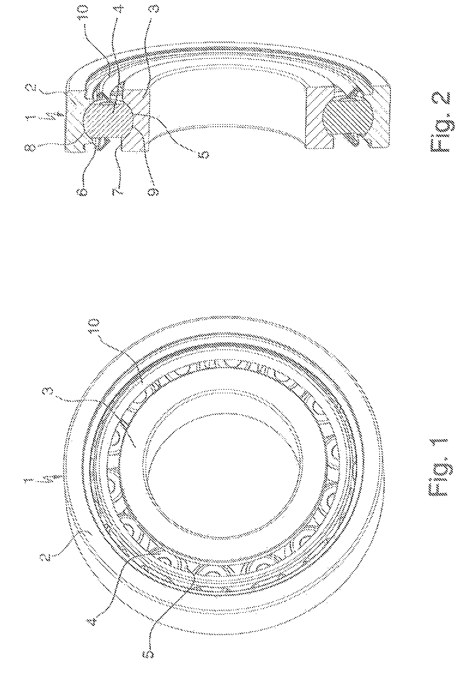
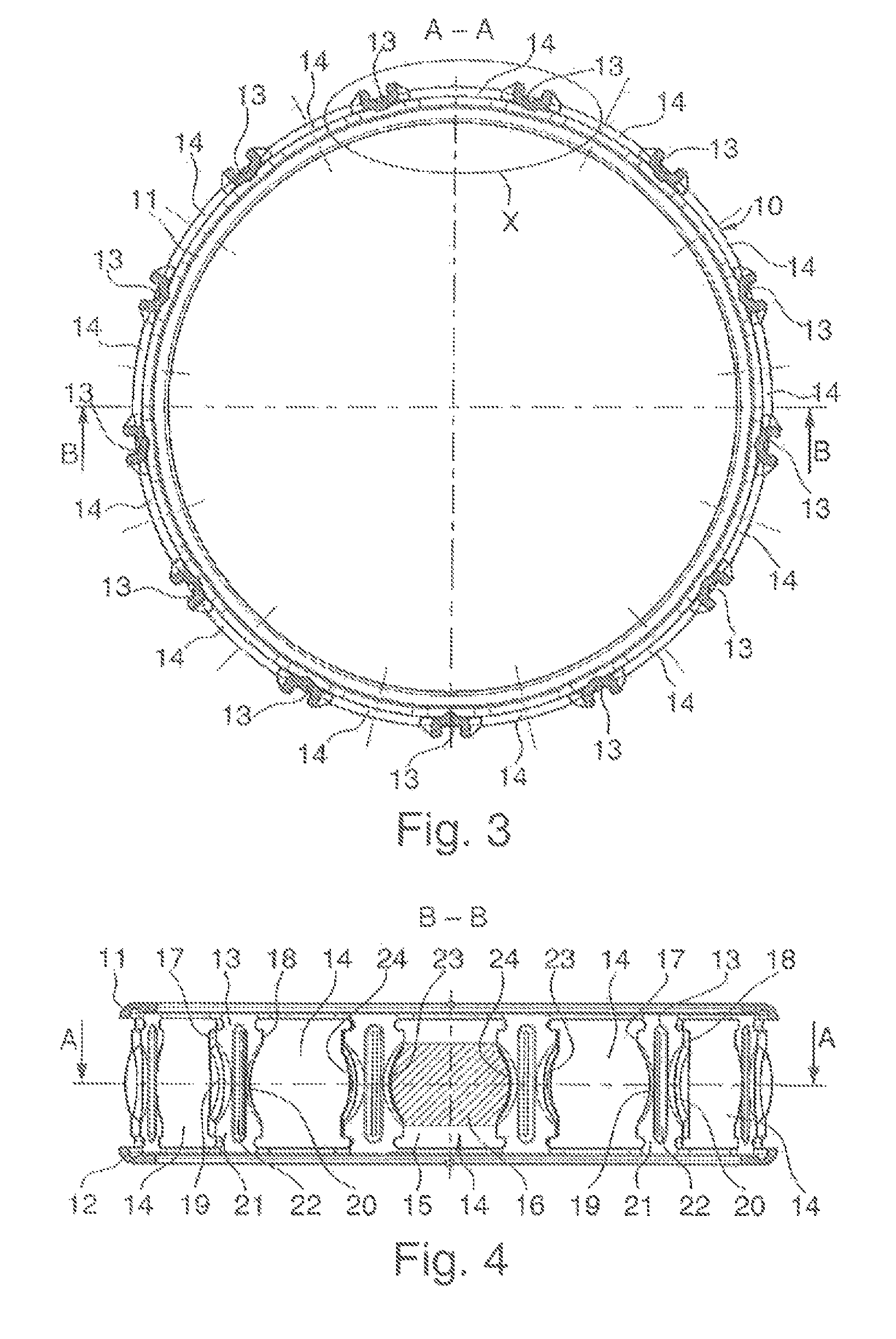
[0017]A ball roller bearing 1 is clearly apparent from FIGS. 1 and 2, and essentially comprises an outer bearing ring 2, an inner bearing ring 3 and a multiplicity of ball rollers 4 arranged between said bearing rings 2, 3. The ball rollers 4 roll on running surfaces 5 in two groove-shaped races 8, 9 machined into the inner side 6 of the outer bearing ring 2 and into the outer side 7 of the inner bearing ring 3 and the ball rollers 4 are held at uniform distances from one another in the circumferential direction by a bearing cage 10. As FIGS. 3 and 4 show, the bearing cage 10 is designed as a window cage, which has two lateral angular flanges 11, 12 of identical diameter, a plurality of pocket webs 13 which connect said angular flanges 11, 12 to one another, and a plurality of cage pockets 14 which are separated from one another by said pocket webs 13. The individual cage pockets 14 of the bearing cage 10 each clearly have a cross-hole shape, which, as illustrated in FIG. 4, is form...
PUM
 Abstract
Description
Claims
Application Information