
Low NOx Gas Burners With Carryover Ignition
a low-nox, burner technology, applied in the direction of burner ignition devices, combustion types, combustion using lump and pulverulent fuel, etc., can solve the problems of unsatisfactory nosub>x /sub>emission requirements of in-shot burner designs, mixing of air and fuel of such systems producing unacceptably high nosub>x /sub>emissions, and ineffective carryover methods, etc., to achieve the effect of improving the flame carry
- Summary
- Abstract
- Description
- Claims
- Application Information
AI Technical Summary
Benefits of technology
Problems solved by technology
Method used
Image

Examples
Embodiment Construction
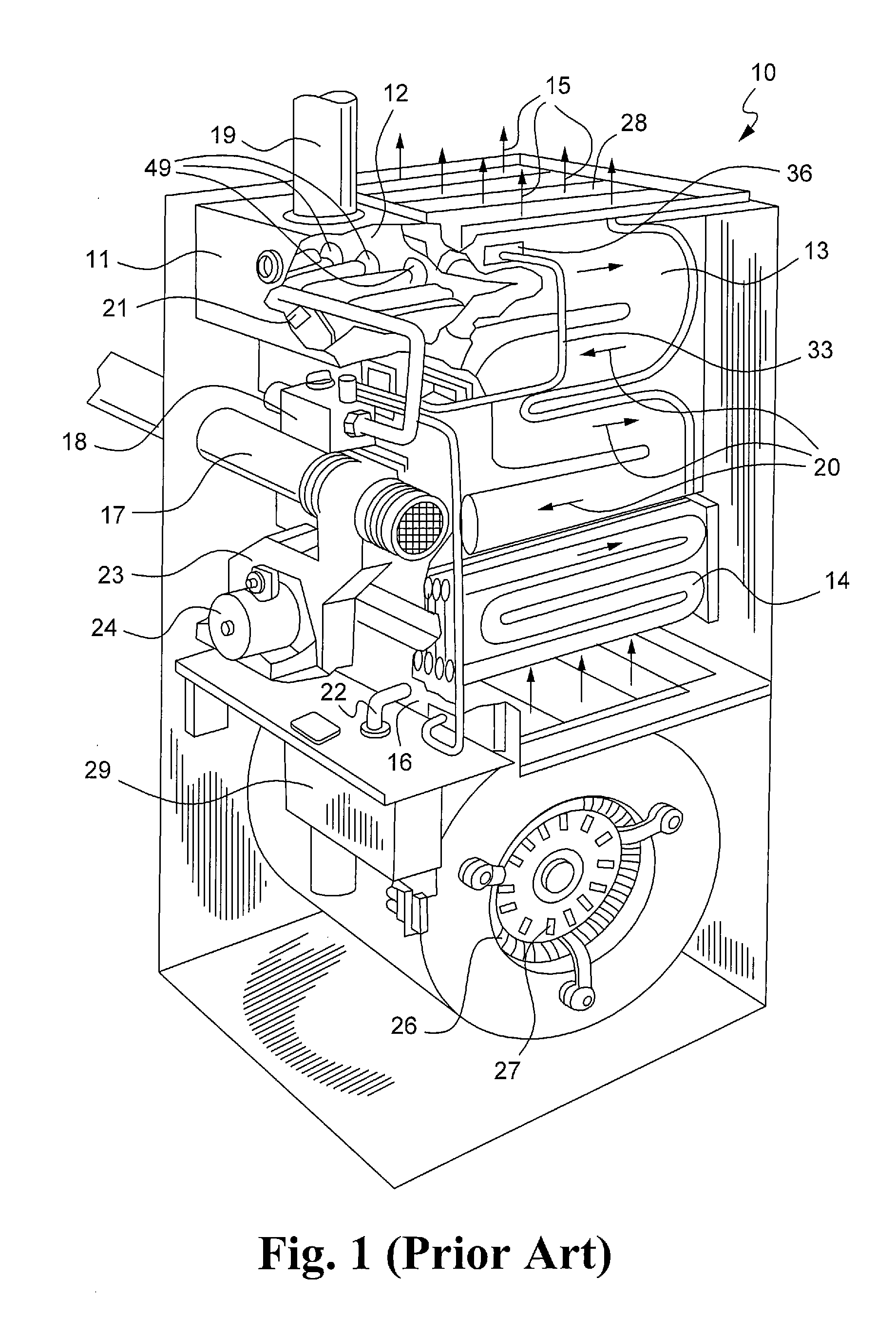
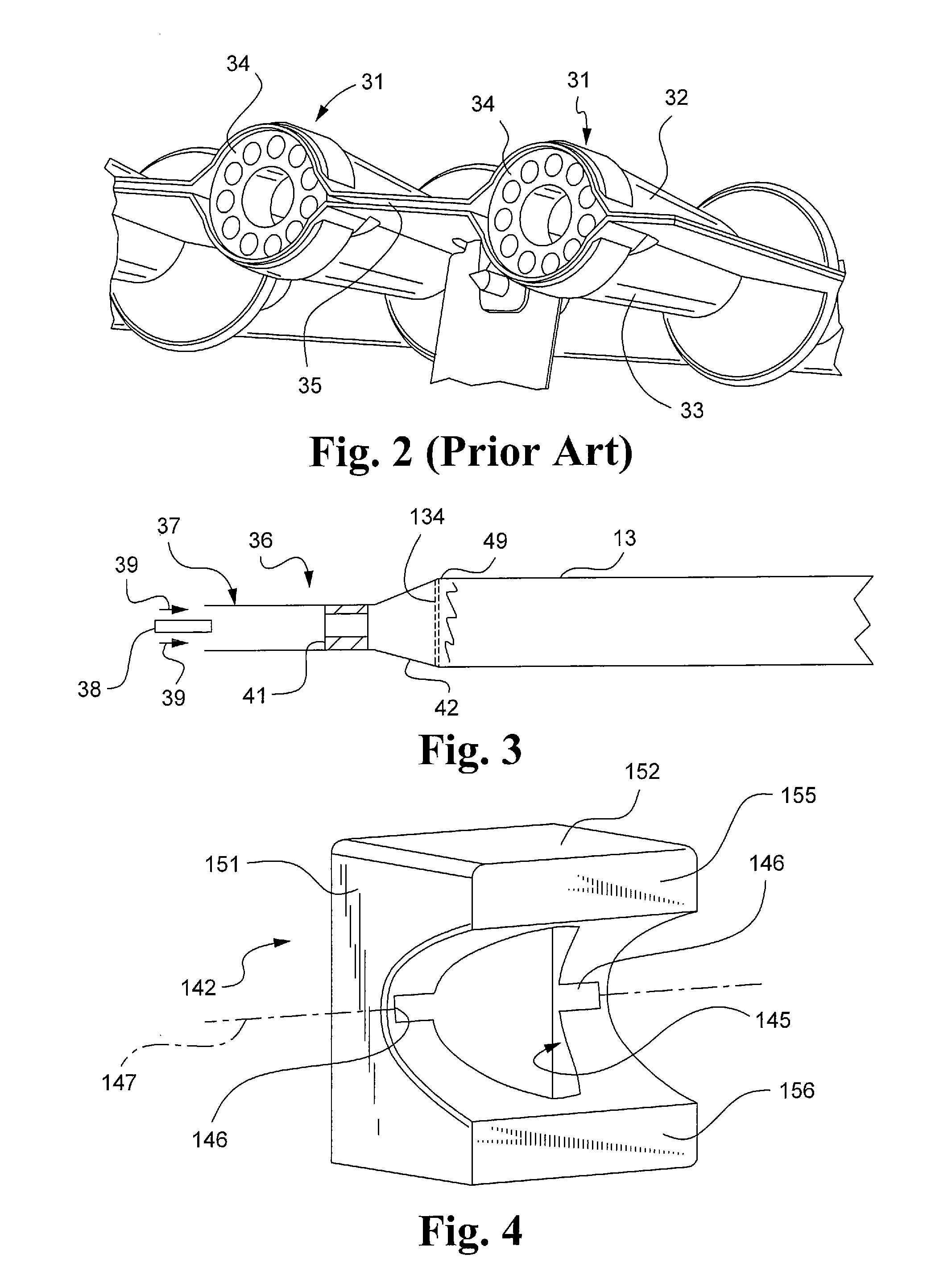
[0023]Referring first to FIG. 1, a sectional gas furnace 10 is shown which comprises a burner assembly 11 with a burner box 12 that is decoupled from the inlets 49 of the primary heat exchanger sections, only one of which can be seen at 13. The primary heat exchanger sections 13 are in fluid communication with corresponding condensing heat exchanger sections 14 whose discharge end is fluidly connected to a collector box 16 and an exhaust vent 17. In operation, a gas valve 18 meters the flow of gas to the burner assembly 11 where combustion air from an air inlet 19 is mixed and ignited by an igniter assembly 21. The hot gas and secondary air are passed through the inlets 49 of the primary heat exchanger sections 13. The primary heat exchanger sections 13 lead to the condensing heat exchanger sections are 14, as shown by the arrows 20.
[0024]The relatively cool exhaust gases then pass through the collector box 16 and exhaust vent 17 before being vented to the atmosphere, while the cond...
PUM
 Abstract
Description
Claims
Application Information