Automatic power supply testing system and method

a testing system and power supply technology, applied in power supply testing, testing circuits, instruments, etc., can solve the problems of time-consuming and inefficien

Inactive Publication Date: 2012-07-19
HON HAI PRECISION IND CO LTD
View PDF3 Cites 16 Cited by
  • Summary
  • Abstract
  • Description
  • Claims
  • Application Information

AI Technical Summary

Problems solved by technology

Thus, after one power supply is finished testing, users need to connect the automatic test device to another power supply to be tested, which is time-consuming and inefficient.

Method used


Image

  • Automatic power supply testing system and method
  • Automatic power supply testing system and method
  • Automatic power supply testing system and method

Examples


Embodiment Construction

[0009]The disclosure, including the accompanying drawings, is illustrated by way of example and not by way of limitation. It should be noted that references to “an” or “one” embodiment in this disclosure are not necessarily to the same embodiment, and such references mean at least one.

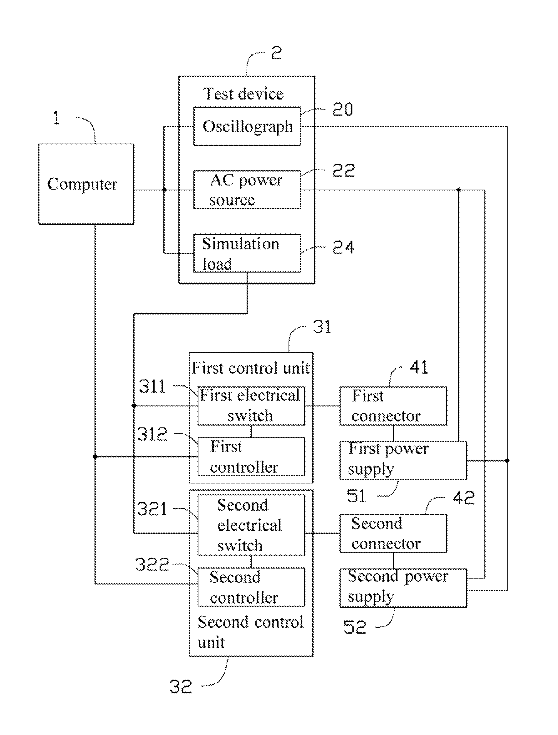
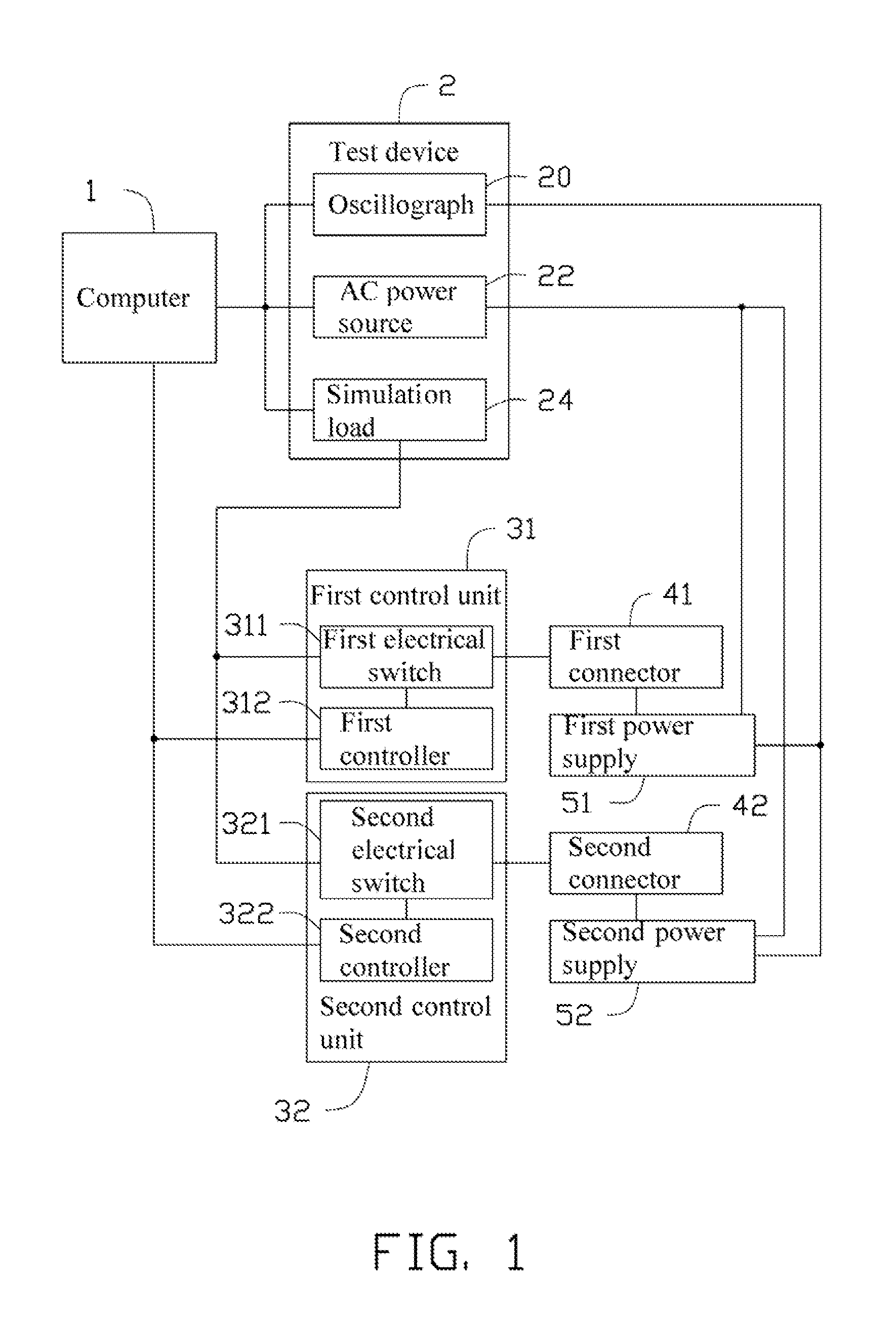
[0010]Referring to the FIGS. 1 and 2, an exemplary embodiment of an automatic power supply testing system for automatically testing the electrical stability of a plurality of power supplies, includes a computer 1, a test device 2, a first control unit 31, a second control unit 32, a first connector 41, and a second connector 42. The plurality of power supply includes a first power supply 51 and a second power supply 52, corresponding to the number of the control units and the connectors.

[0011]The test device 2 includes an oscilloscope 20, an alternating current (AC) power source 22, and a simulation load 24. The computer 1 is connected to the oscilloscope 20, the AC power source 22, and the simulation ...


PUM


Abstract

An automatic power supply testing system records a preset test order of first and second power supplies with a recording module. The automatic power supply testing system controls a first control unit to connect a first connector connected to the first power supply to a simulation load to test the first power supply according to the preset test order by a determination control module and obtains a first test result. The automatic power supply testing system controls a second control unit to connect a second connector connected to the second power supply to the simulation load to test the second power supply after determining that the first test result is displayed and obtain a second test result. A display module displays the electrical stability of the first and second power supplies.

Description

BACKGROUND[0001]1. Technical Field[0002]The present disclosure relates to an automatic testing system and method for a plurality of power supplies.[0003]2. Description of Related Art[0004]Automatic test devices are used to test electrical stability of power supplies. However, one test device is used to test one power supply at any one time. Thus, after one power supply is finished testing, users need to connect the automatic test device to another power supply to be tested, which is time-consuming and inefficient.BRIEF DESCRIPTION OF THE DRAWINGS[0005]Many aspects of the embodiments can be better understood with reference to the following drawings. The components in the drawings are not necessarily drawn to scale, the emphasis instead being placed upon clearly illustrating the principles of the present embodiments. Moreover, in the drawings, like reference numerals designate corresponding parts throughout the several views.[0006]FIG. 1 is a block diagram of an exemplary embodiment o...

Claims


Application Information

Patent Timeline
Patent Type & Authority Applications(United States)
IPC IPC(8): G01R31/40
CPCG01R31/40
Inventor CHEN, CHI-WEN
Owner HON HAI PRECISION IND CO LTD
Why Eureka
Try Eureka