

Universal clutch alignment tool
- Summary
- Abstract
- Description
- Claims
- Application Information
AI Technical Summary
Benefits of technology
Problems solved by technology
Method used
Image

Examples
Embodiment Construction
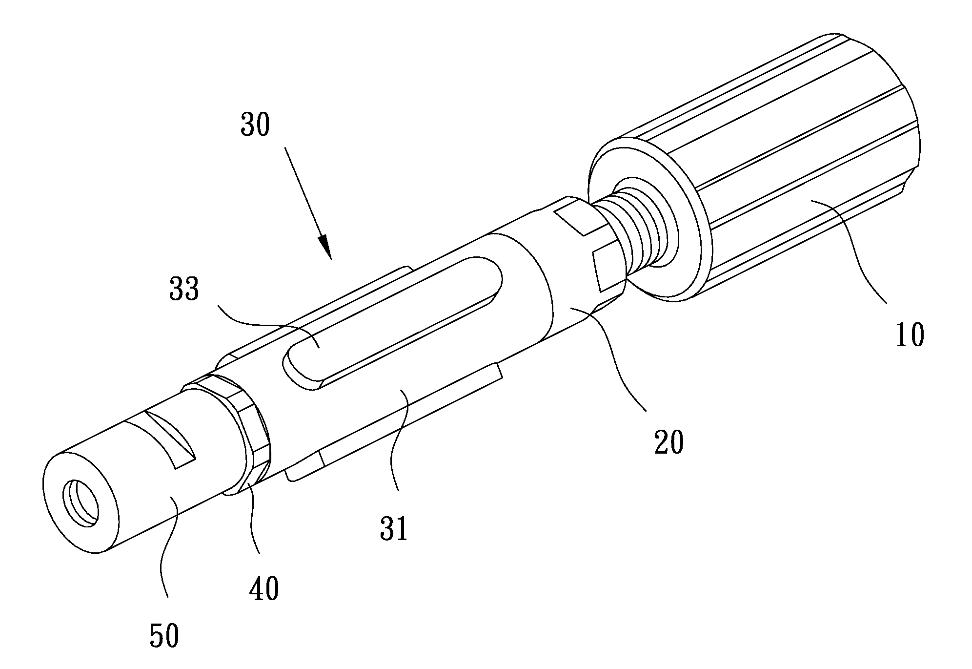
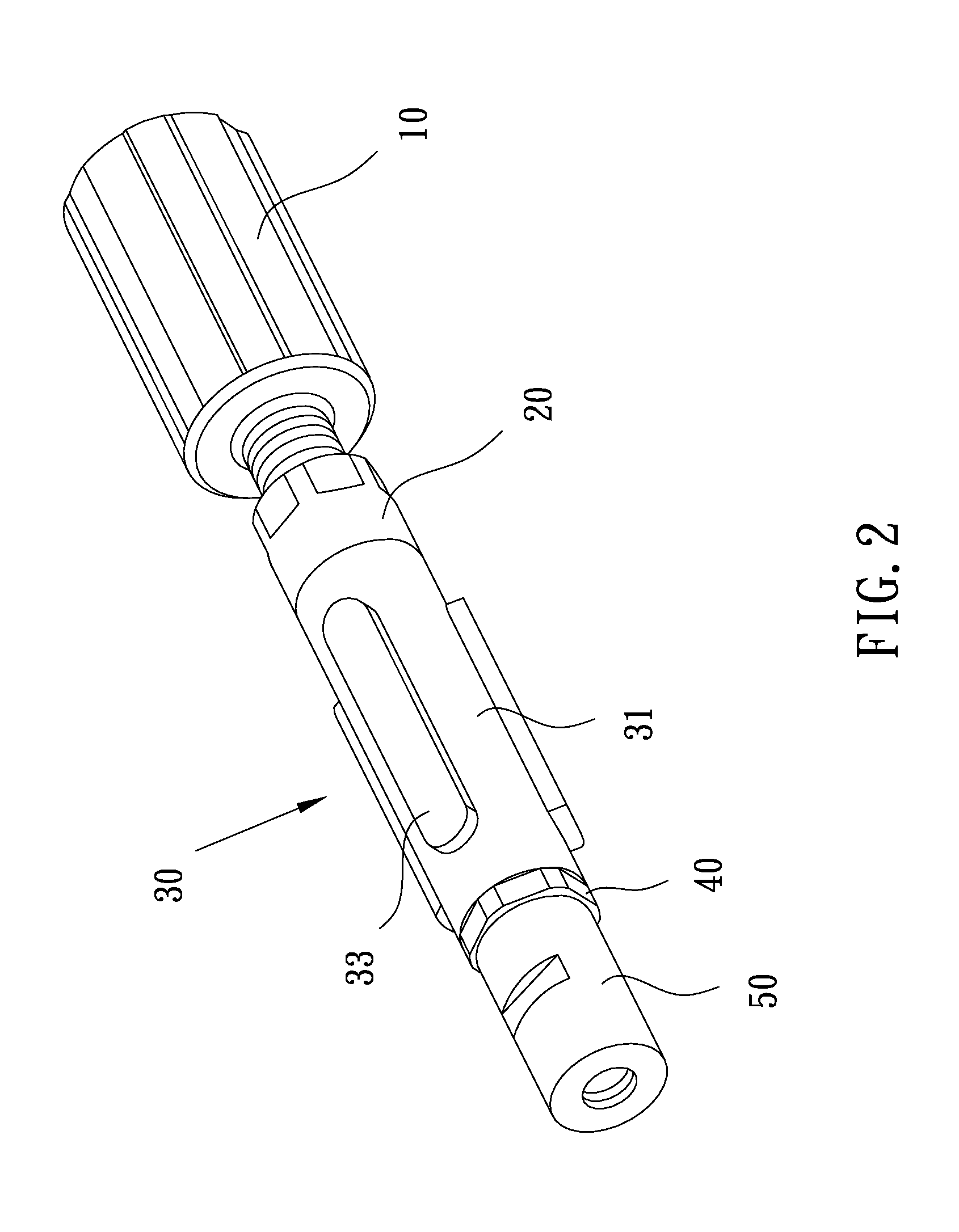
[0019]Please refer to FIGS. 2 to 5. The present invention relates to a universal clutch alignment tool, which includes a tool rod 10, an adjustment nut 20, a connecting mechanism 30, a screw rod 40, and a positioning pipe 50. The adjustment nut 20, the connecting mechanism 30, the screw rod 40 and the positioning pipe 50 are sequentially assembled at a front end of the tool rod 10. With this structure, an assembling tool for assembling or disassembling a clutch is obtained.
[0020]The tool rod 10 is an elongate rod. One end of the tool rod 10 is configured to be held by a user, and the other end is provided with an outer threaded section 11 for threadedly combining with the adjustment nut 20.
[0021]An inner edge of one end of the adjustment nut 20 corresponding to the tool rod 10 is formed with an inner threaded hole 21 for threadedly combining with the outer threaded section 11. The other end of the adjustment nut 20 is formed with an outer threaded portion 22 for threadedly combining...
PUM
 Abstract
Description
Claims
Application Information