Machining device

a technology of machining device and clamping surface, which is applied in the direction of manufacturing tools, metal-working machine components, woodworking apparatus, etc., can solve the problems of limited free clamping surface available, workpieces cannot be readily machined by means of the machining device designed in this manner, and only on the upper and lower support surfaces. , to achieve the effect of efficient machining

Active Publication Date: 2017-10-19
HOMAG GMBH
View PDF1 Cites 4 Cited by
  • Summary
  • Abstract
  • Description
  • Claims
  • Application Information

AI Technical Summary

Benefits of technology

This patent is about a machining device that can hold and position workpieces in three dimensions. It can have multiple workpiece tables and supply them with workpieces simultaneously. This allows for more efficient and quality machining. The device can also have a fitting or RFID chip to supply any necessary elements to the workpiece. Overall, this patent aims to improve the machining process by making it faster, more efficient, and flexible.

Problems solved by technology

If, however, a workpiece with a contour which differs in height on both opposite side edges is intended to be machined therewith because, for example, the respective lower edge is intended to be formed offset from the other one, this workpiece cannot readily be machined by means of the machining device designed in this manner because, for the rechucking from one workpiece table to the other workpiece table, there is no defined rechucking state.
This leads to only very limited free clamping surfaces still being available on the window frame parts for holding the window frame parts in the clamping jaws in the workpiece holder for the machining of the workpiece, wherein this problem occurs evermore frequently if a first longitudinal side of the window frame part has already been profiled.
Although this has the advantage that the workpiece can maintain a constant height level in the vertical direction and optionally also a constant position in the lateral direction during clamping and rechucking operations, it also has the disadvantage, however, that clamping can be undertaken only on the upper and lower support surfaces.

Method used


Image

  • Machining device
  • Machining device
  • Machining device

Examples


Embodiment Construction

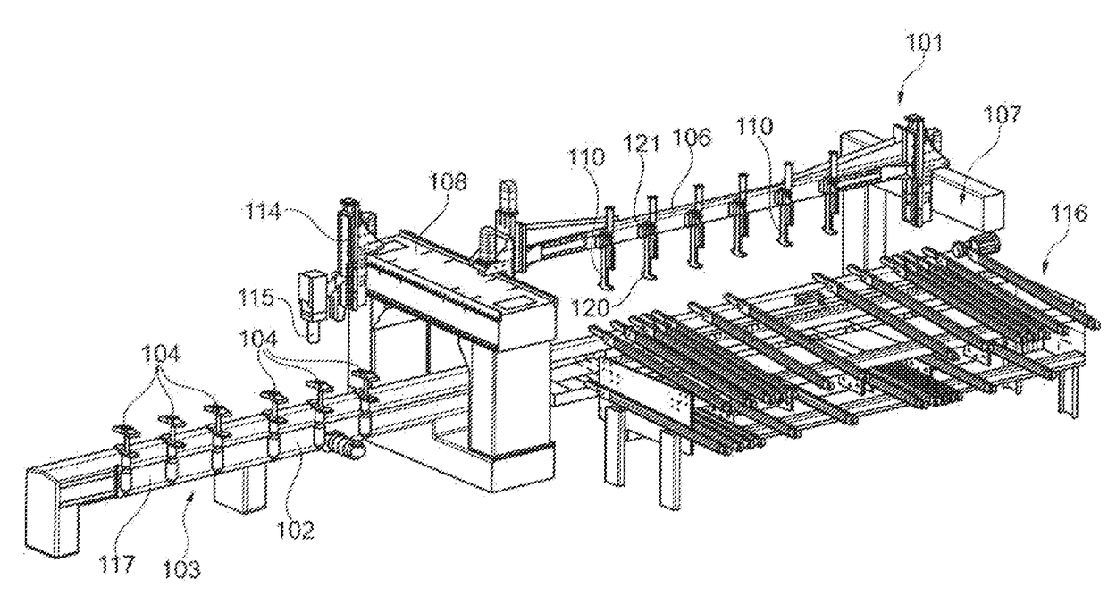
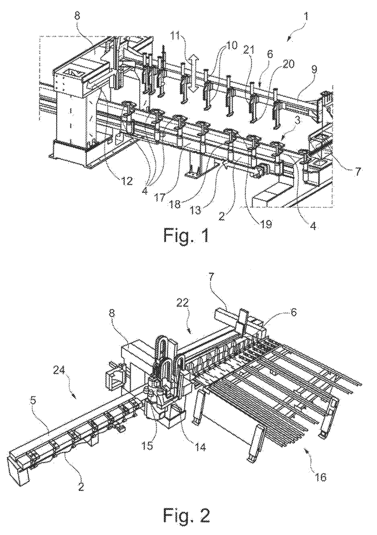
[0065]FIGS. 1 and 2 show a machining device 1, in particular for machining workpieces 5 made of wood, wood materials, plastic or the like. The workpieces 5 here can be, for example, more elongate, beam-like workpieces or more flat, more two-dimensional, board-like workpieces.

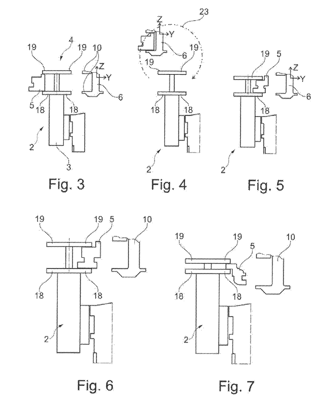
[0066]The machining device 1 has a workpiece table 2 with a workpiece holder 3 with clamping elements 4 for clamping a workpiece, by means of which workpieces 5 can be securely held for machining. The workpiece table 2 is preferably designed connected to an advancing unit, by means of which the workpiece table 2 is designed so as to be shiftable in direction 13. The direction 13 is advantageously oriented perpendicular here to the direction 11 and to the direction 12.

[0067]Furthermore, a supply device 6 is provided which serves to supply a workpiece 5 to the workpiece holder 3 of the workpiece table 2 and to place the workpiece 5 on the workpiece table 2.

[0068]Furthermore, a device framework is provided on which...


PUM


Abstract

The invention relates to a machining device, in particular for machining workpieces of wood, wood materials, plastic or the like, comprising a workpiece table with a workpiece holder for holding at least one workpiece, and a feeding device for supplying at least one workpiece to the workpiece table, wherein the workpiece can be positioned in three dimensions with respect to the workpiece table. The invention further relates to a corresponding method.

Description

TECHNICAL FIELD[0001]The invention relates to a machining device, in particular for machining workpieces made of wood, wood materials, plastic or the like, in particular according to the preamble of claim 1, and to a method for operating such a machining device.PRIOR ART[0002]Machining, devices for machining workpieces, in particular for machining work pieces made of wood, wood materials, plastic or the like, are widely known in the prior art. Such machining devices customarily have a workpiece table with a workpiece holder by means of which a workpiece can be arranged and can be held at least temporarily by clamping in order to machine the workpiece during the clamping holding. Such workpiece tables with workpiece holders can be designed to be substantially stationary or to be shiftable by means of advancing devices.[0003]In the case of a substantially stationary design of the workpiece table with the workpiece holder, the tool for machining the workpiece can be brought up to the w...

Claims


Application Information

Patent Timeline
Patent Type & Authority Applications(United States)
IPC IPC(8): B27C5/06B27C9/02B25B5/00
CPCB27C5/06B27C9/02B25B5/003B27M1/08B25B5/142B25B1/02B25B1/18B23Q3/00
Inventor FRIESE, STEFANSCHMIEDER, VOLKERSTURM, CHRISTIAN
Owner HOMAG GMBH
Why Eureka
Try Eureka