Resilient pad for railroad vehicle

a technology for rail vehicles and pads, applied in the field of pads, can solve the problems of needing to replace wear plates, weaken frames at load-bearing locations, and damage to frame surfaces, so as to reduce the installation effort, prevent or minimize the aforesaid problems, and facilitate the handling of load forces and stresses

Active Publication Date: 2012-07-26
PENNSY CORP
View PDF0 Cites 38 Cited by
  • Summary
  • Abstract
  • Description
  • Claims
  • Application Information

AI Technical Summary

Benefits of technology

[0011]According to a preferred embodiment, a resilient pad for use in connection with a pedestal wear plate is provided. The pad prevents or minimizes the aforesaid problems associated with plate tensile stress bending and cracking, while not introducing any significant increase in

Problems solved by technology

In service, movement or frictional sliding may occur between the bearing adapter and the clip-on pedestal wear plate, which may cause damage to the clip-on pedestal wear plate, resulting in the need to replace the wear plate.
This condition also may result in the loss of the freely pivoting end condition and may weaken the frame at a load-bearing location.
Repair of the frame surface is both expensive and time-consuming, since the worn surface must be ground down to return it to a flat condition.
The amount of grinding allowed, however, is limited by structural considerations; after the limit has been reached, the side frame casting is condemned.
Replacing the clip-on wear plate is less expensive, but still costly, as it involves removing the railroad car from service and jacking the car so that the broken clip-on wear plates can be removed and replaced.
If this opposing frictional force is insufficient to resist this movement, additional bending load and stress are imposed on the side lips of the wear plate.
The sensitivity to imbalance in these frictional forces, and hence the tendency to impose stress and load on the plate side lips, increases with heavily loaded rail cars such as coal cars.
The result of the total installation related tensile stresses in combination with stress related to bearing adapter friction can result in a significant sho

Method used


Image

  • Resilient pad for railroad vehicle
  • Resilient pad for railroad vehicle
  • Resilient pad for railroad vehicle

Examples


Embodiment Construction

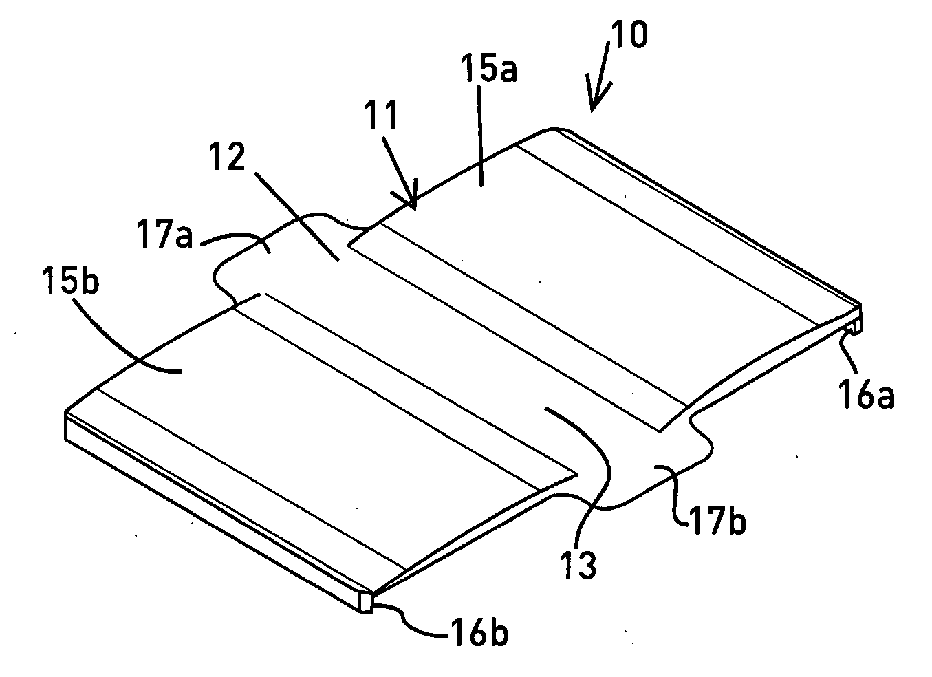
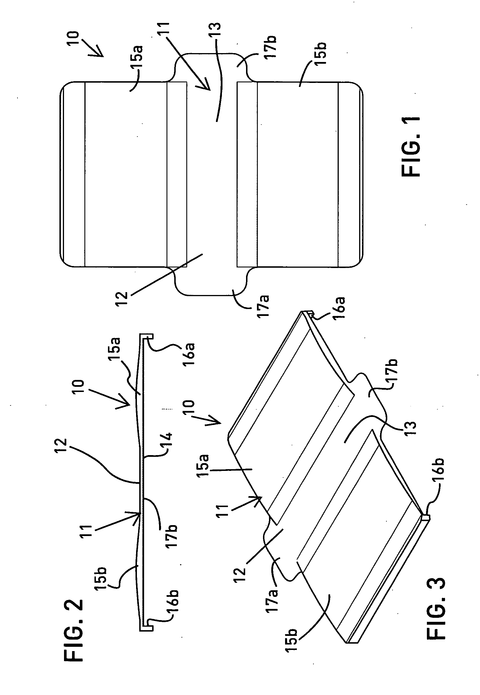
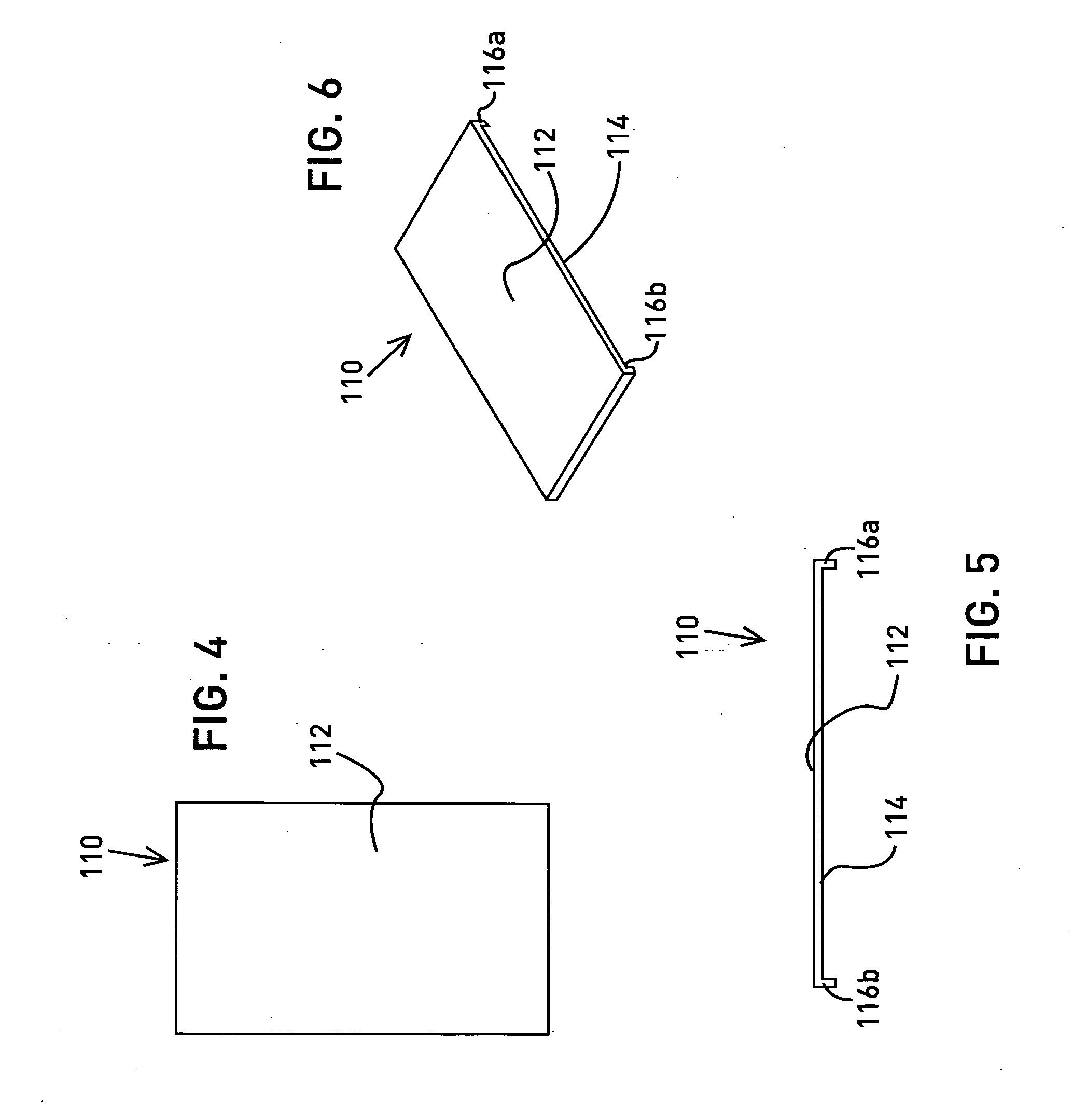
[0035]Referring to FIGS. 1-3, a preferred embodiment of a pad 10 for a wear plate is shown having a main body 11 with an upper surface 12 and lower surface 14. According to a preferred embodiment, the lower surface 14 is configured as a substantially planar surface. Preferably, the upper surface 12 is provided having force handling means comprising a force handling configuration. According to a preferred embodiment, the force handling means is illustrated comprising raised portions 15a, 15b of the surface 12. The raised portions 15a, 15b preferably are bulged and are disposed transversely on the pad 10 in a spaced apart relation to each other. As illustrated in FIGS. 1-3, the pad 10 has a spacing portion 13, with the raised portions 15a, 15b being provided on opposite sides of the spacing portion 13. The pad 10 preferably includes a feature for holding and aligning the pad 10 in an appropriate location for installation. Holding means for facilitating holding and aligning of the pad ...


PUM


Abstract

A resilient pad having a base with two side arms and two side lips for resiliently holding the base on a pedestal wear plate, the pad being configured with dome shaped portions disposed substantially perpendicular to the direction of the pad and being spaced apart from each other, where the pad, when installed with a pedestal wear plate serves to improve the force load handling and preferably re-distributes the load bearing surface from the edges and center of the adapter to the flat load bearing surface of the adapter, thus eliminating load on areas that have no support. Because the spring arms do not depend on bending of the base for their resiliency, the pad of the invention provides improved service stress capabilities and allows for longer life of the wear plate.

Description

BACKGROUND OF THE INVENTION[0001]1. Field of the Invention[0002]This invention relates to a pad for handling force loads to prevent wear on the load bearing surface of a pedestal of a rail vehicle, and more particularly relates to improvements in force handling in an arrangement where a wear plate specifically designed for convenient and removable installation in the pedestal opening of a railway side frame is used in order to prevent wear on the load bearing surface of the pedestal.[0003]2. Brief Description of the Related Art[0004]For the sake of brevity, the teachings and complete disclosures of previous U.S. Pat. Nos. 3,897,736 and 4,203,371 are incorporated herein by reference. In many cases, a bearing adapter is provided over the axle bearing, said adapter having a slightly arcuate top surface which bears directly against a corresponding downwardly facing surface in the pedestal opening of the side frame. This arcuate top surface provides the wheel and axle with a freely pivot...

Claims


Application Information

Patent Timeline
IPC IPC(8): B61F5/50
CPCB61F5/32
Inventor TAVARES, MANUELSCHMIDT, MICHAEL JAMES
Owner PENNSY CORP
Why Eureka
Try Eureka