
Ice skate blade assembly

a technology of ice skate blades and parts, applied in the direction of skates, couplings, manufacturing tools, etc., can solve the problems of increasing the complexity of its construction and operation, the need to use two or more fastener means, and the cumbersome and time-consuming process of changing the ice skate blades for users

Active Publication Date: 2012-07-26
BAUER HOCKEY LLC
View PDF2 Cites 18 Cited by
  • Summary
  • Abstract
  • Description
  • Claims
  • Application Information

AI Technical Summary

Problems solved by technology

However, a deficiency in this second prior assembly is that the replacement of the blade usually requires demounting the blade holder from the skate boot in order to gain access to the threaded fastening means so that the blade may be released from the blade holder.
Another deficiency in the first and second prior assemblies described above is the need to use two or more fastener means.
The use of these fastener means renders the process of changing the ice skate blade both cumbersome and time-consuming for the user.
However, a known deficiency in the third prior assembly is that the replacement of the blade requires passing a tool through a hole provided in the sole of the skate boot to access the nut screwed on the threaded portion of the fastener in order to disengage the head of the fastener means from the bore hole and thus release the blade from the blade holder.
A known deficiency of this assembly is that it comprises several pieces, thereby increasing the complexity of its construction and operation.
However, a known deficiency of this assembly is that it comprises several separate pieces, thereby increasing the complexity of its construction and operation.

Method used


Image

  • Ice skate blade assembly
  • Ice skate blade assembly
  • Ice skate blade assembly

Examples


Embodiment Construction

[0023]To facilitate the description, any reference numeral designating an element in one figure will designate the same element if used in any other figures. In describing the embodiments, specific terminology is resorted to for the sake of clarity but the invention is not intended to be limited to the specific terms so selected, and it is understood that each specific term comprises all equivalents.

[0024]Unless otherwise indicated, the drawings are intended to be read together with the specification, and are to be considered a portion of the entire written description of this invention. As used in the following description, the terms “horizontal”, “vertical”, “left”, “right”, “up”, “down” and the like, as well as adjectival and adverbial derivatives thereof (e.g., “horizontally”, “rightwardly”, “upwardly”, “radially”, etc.), simply refer to the orientation of the illustrated structure. Similarly, the terms “inwardly,”“outwardly” and “radially” generally refer to the orientation of ...


PUM


Abstract

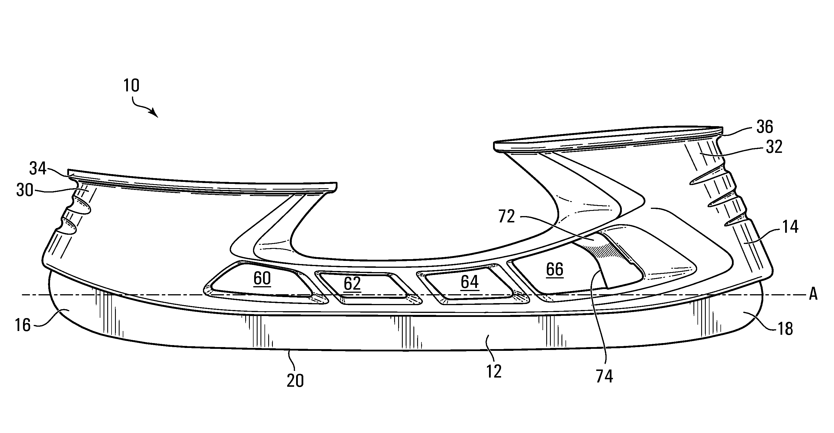
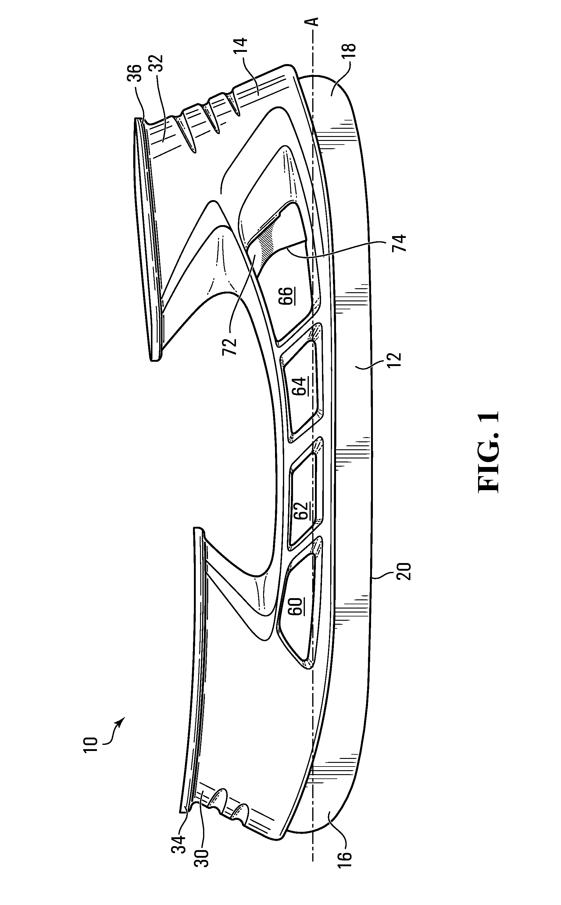
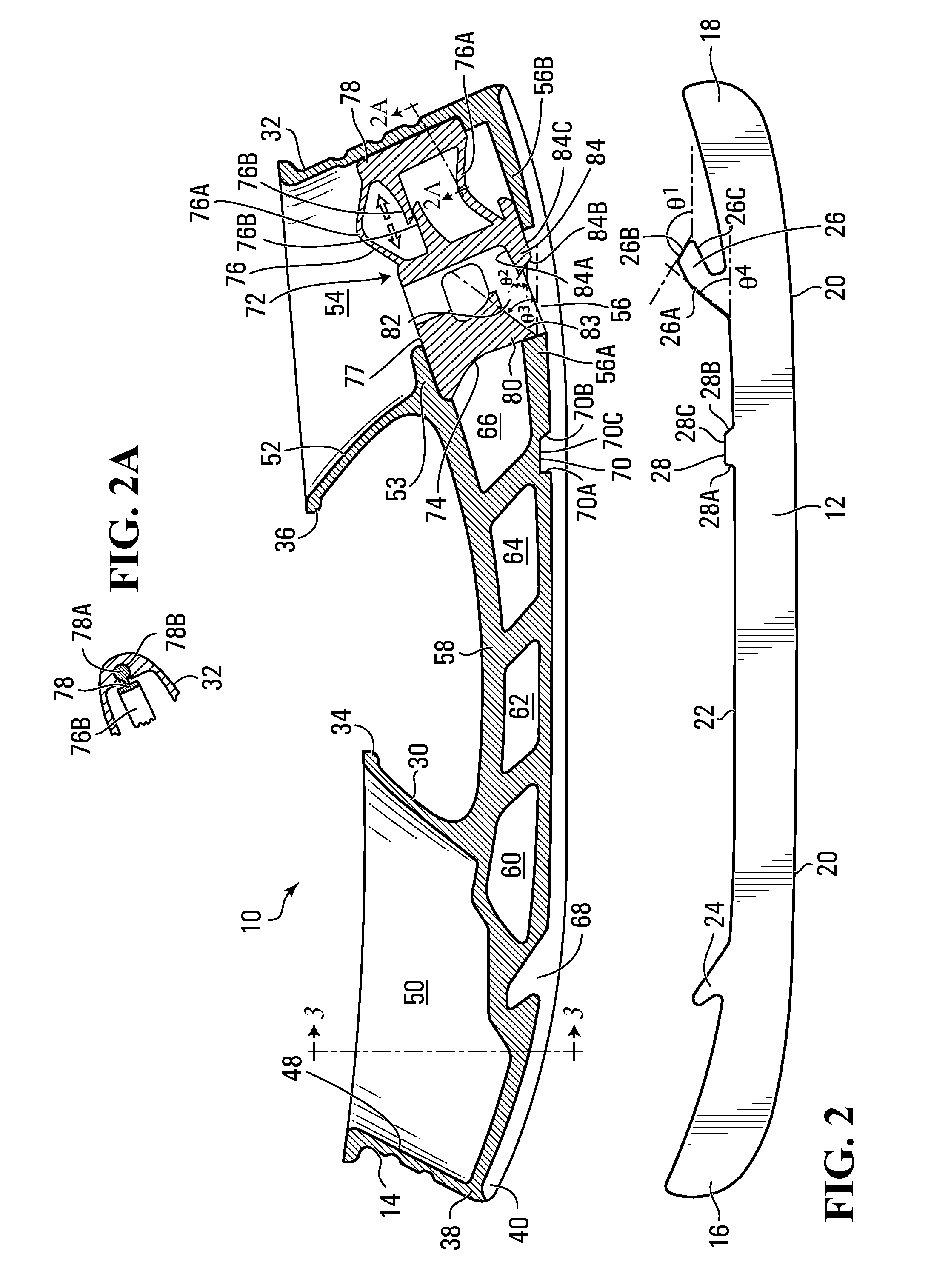
An ice skate blade assembly comprising: (a) an ice skate blade comprising first and second ends, an ice contacting surface and an upper edge opposed to the ice contacting surface, the upper edge comprising first and second hooks projecting upwardly proximate to one of the first and second ends respectively, the second hook having an upper surface, an end and a bottom surface; (b) a blade holder having first and second pedestals and a bottom portion having a longitudinal groove extending therealong for receiving the upper edge of the ice skate blade and wherein the bottom portion further defines a recess extending upwardly from the longitudinal groove for receiving the first hook and wherein the second pedestal has an inner surface defining a cavity with a bottom aperture opens to the longitudinal groove; and (c) a single actuator at least partially mounted within the cavity, the single actuator having a wall accessible by a finger of a user, a resilient portion having an end wall facing a section of the inner surface of the second pedestal and a base with an inner wall and a bottom wall having an upper surface, an end and a bottom surface, wherein the inner wall and the bottom wall define therebetween a channel opens to the bottom aperture for receiving the second hook.

Description

FIELD OF THE INVENTION[0001]The present invention relates to an ice skate blade assembly comprising a skate blade attachment system that allows to a user to quickly secure the ice skate blade to the blade holder and to quickly release the ice skate blade from the blade holder. The attachment system is easy for the user to use and does not require the assistance of hand tools. Moreover, the attachment system allows the user to replace ice skate blades without first having to remove the skate from his / her foot.BACKGROUND OF THE INVENTION[0002]Forming ice skate assemblies with a provision for the replacement of the ice skate blade is well known in the art.[0003]Commonly, such assemblies comprise a blade holder molded from a thermoplastic material with a longitudinal groove extending therealong and within which the ice skate blade is received.[0004]In accordance with a first prior assembly, the ice skate blade is locked to the blade holder by two or more threaded fastener means (such as...

Claims


Application Information

Patent Timeline
Patent Type & Authority Applications(United States)
IPC IPC(8): A63C1/30
CPCY10T403/604Y10T403/1641A63C1/303
Inventor CORBEIL, JEAN-FRANCOISPAYEUR, CONRADLABONTE, IVANDUBOIS, SEBASTIEN
Owner BAUER HOCKEY LLC
Learn More