Flexor with extending flexor arm

a flexor and flexor arm technology, applied in the field of flexors with extending flexor arms, can solve the problems of reducing rarely reaching the curve, and increasing so as to reduce the stress on skiers, increase the efficiency of skiing action, and increase the maximum rotation of ski boots

Active Publication Date: 2012-07-26
ROTTEFELLA AS
View PDF6 Cites 7 Cited by
  • Summary
  • Abstract
  • Description
  • Claims
  • Application Information

AI Technical Summary

Benefits of technology

[0011]In particular, it is advantageous if the flexor, or simply merely the extending flexor arm, is made from a material which is generally elastic. That is, that the material can be elastically bent and / or compressed but that the material will maintain the memory of the original shape, and return thereto after removal of any force. As would be clear from this, the linear force versus displacement section to the curve would relate to a rotation of the extension arm, as described above, and the exponential section to the curve would relate to a compression of the extension arm, and also to a degree sections of the flexor in the region of the point of connection. Further, this may relate only to the compression and stretching of the flexor and flexor arm around the point of contact between these two, without the need for the flexor arm to strike a further surface and be compressed. Obviously, as only parts of the flexor are being rotated and compressed and stretched, the operation is more energy efficient. That is, there is less energy being lost to heat from excessive compression of the flexor, as only a section thereof is undergoing deformation. One could consider that as the flexor arm is rotating, the action is somewhat spring-like, as the return force is essentially the springing back into shape of the flexor, thus leading to a better energy characteristic with less losses.
[0027]One final consideration is that in general the skier will only be able to apply a certain force to the flexor before it either hurts too much, or the maximum rotation has been reached. As will be abundantly clear from the curves in FIG. 6, the option of the flexor which has a linear force versus displacement section leading into the exponential section is desirable, as for a certain applied force the maximum rotation of the ski boot is greatly increased. That is, the skier will be able to rotate the ski boot to a much larger rotation angle for the same applied force, which not only increases the efficiency of the skiing action, but also reduces the stress on the skier as the action may still be improved with greater rotation angles, without the use of such a high force.

Problems solved by technology

This leads to a very steep gradient in the force versus displacement curve, and is essentially a result of the flexor arm being unable to rotate further because of the binding or the like.
In each of these cases, drawbacks exist.
This is rarely reached, however, as the skier is then providing a large force on the flexor in order to obtain the desired rotation and compression, which will become extremely painful after a short time.
In order to achieve this, however, the return force generated by the flexor will generally be reduced at lower rotation angles, which is undesirable from the point of the skier.
With regard to the spring option, whilst this gives a tuneable force versus displacement curve in the linear portion, the sudden discontinuity is a jarring force felt by the skier, in particular in their toes, which is uncomfortable and undesirable for the skier.
Additionally, the lack of feedback at the high rotation angles of the ski boot, i.e. the fact that the high rotation angles do not give rise to high resistive forces, leads to the skier feeling disconnected from the ski and snow.
This lack of connection is quite disorienting for skiers used to such feedback, and is an undesirable aspect which needs considering.

Method used


Image

  • Flexor with extending flexor arm
  • Flexor with extending flexor arm
  • Flexor with extending flexor arm

Examples


Embodiment Construction

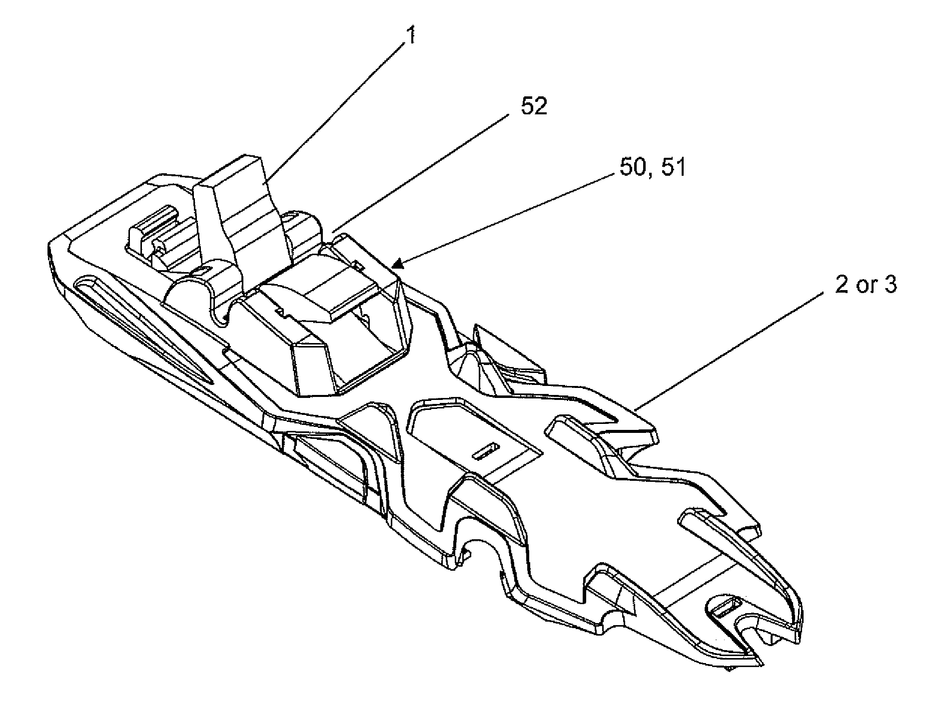
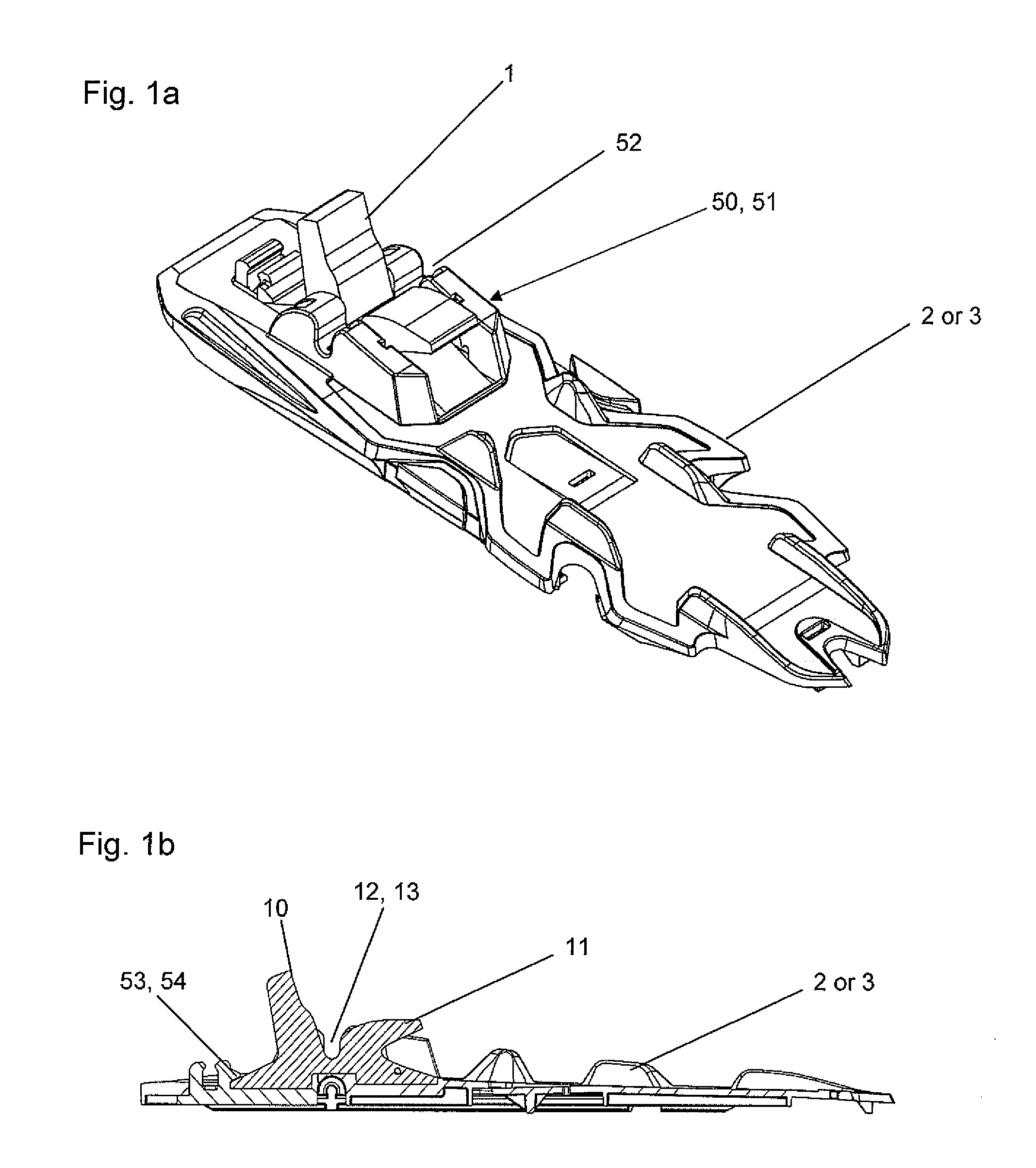
[0037]Looking at FIG. 1a, a ski binding 2 incorporating the flexor 1 of the current disclosure is shown in perspective form. As can be seen from the Figure, the flexor 1 is intended to be positioned within the binding 2 in the region surrounding the attachment of a ski boot 7 to the binding 2. Whilst FIG. 1a shows the flexor 1 integrated with a ski binding 2, it is also conceivable for the flexor 1 to be incorporated with a mounting plate 3 for a ski 4. The ski binding 2 and mounting plate 3 as well as the flexor 1, are intended for use with cross country or touring skis 4. In cross country or touring skiing the skier is attached to the ski 4 in a rotatable manner. In order to allow for appropriate skiing action, it is necessary for the ski boot 7 to be fixed to the ski 4, usually by means of the binding 2 or mounting plate 3, and to be able to rotate around the toe portion of the ski boot 7.

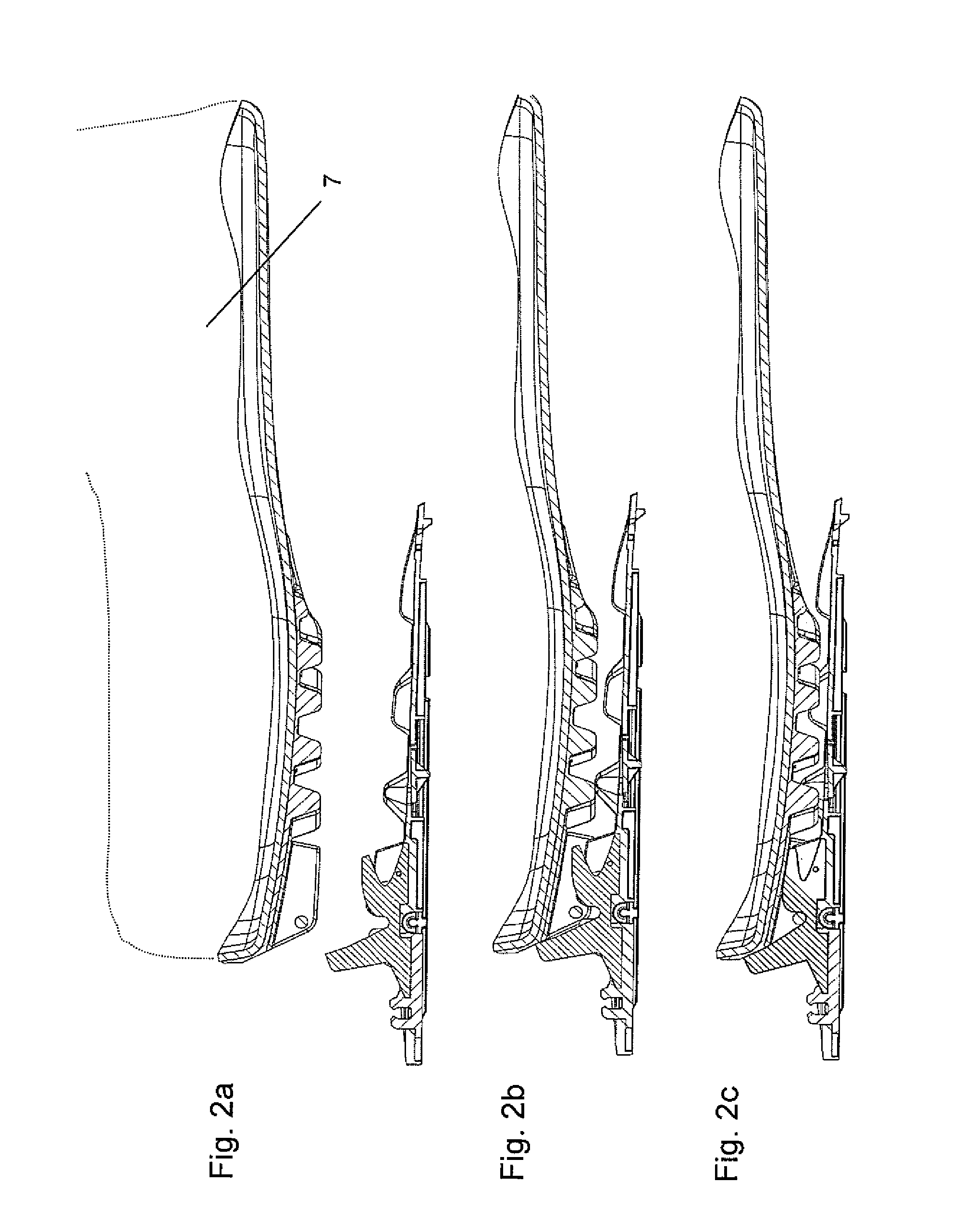
[0038]As has been discussed above, rotation of the ski boot 7 during skiing is typically per...


PUM


Abstract

A flexor (1) for use in a ski binding (2) or mounting plate (3) for a cross country or touring ski (4) is described. This comprises: an extending flexor arm (10) and a holding and positioning portion (20), wherein the extending flexor arm (10) is connectable to, or integral with, the holding and positioning portion (20) such that the extending flexor arm (10) can rotate and / or displace with respect to the holding and positioning portion (20) around the point of connection (21) between the two. The extending flexor arm (10) is formed such that the amount of displacement of the extending flexor arm (10) as a result of an applied force (N) acting thereon follows a substantially linear relationship (30), up to a first desired amount of displacement (31). For a displacement of the extending flexor arm (10) greater than the first desired amount of displacement (31), the amount of displacement of the extending flexor arm (10) as a result of an applied force (N) acting thereon follows an approximately exponential relationship (32).

Description

BACKGROUND TO THE INVENTION[0001]In cross country or touring skiing, the ski boot of the skier is typically attached in a rotatable manner to the ski. Often the ski boot will be provided with a pin, or the like, at the front portion thereof, which fits in an appropriately shaped housing section on the binding or mounting plate attached to the ski. The action of cross country skiing involves the skier removing the heel section of the boot from the top surface of the ski whilst performing the walking type manoeuvre. In order to increase the effectiveness of cross country skiing, it is common to provide some sort of restorative flexor in the region of the toe portion of the ski boot. This flexor acts to counter the rotation of the ski boot where the heel leaves the top surface of the ski, such that the heel of the ski boot will tend to be pushed back into contact with the top surface of the ski.[0002]Numerous prior art flexors have been proposed, the most simple being a compression fle...

Claims


Application Information

Patent Timeline
Patent Type & Authority Applications(United States)
IPC IPC(8): A63C1/04A63C9/00A63C9/20
CPCA63C9/20
Inventor WOLLO, EVENHOLM, THOMASSVENDSEN, OYVAR
Owner ROTTEFELLA AS
Why Eureka
Try Eureka