Coil component
a coil and component technology, applied in the direction of transformer/inductance details, inorganic material magnetism, electrical equipment, etc., can solve the problems of increasing the height dimension of the coil component, and the method does not meet the demand for height reduction, so as to achieve the effect of reducing heigh
- Summary
- Abstract
- Description
- Claims
- Application Information
AI Technical Summary
Benefits of technology
Problems solved by technology
Method used
Image

Examples
embodiment 1
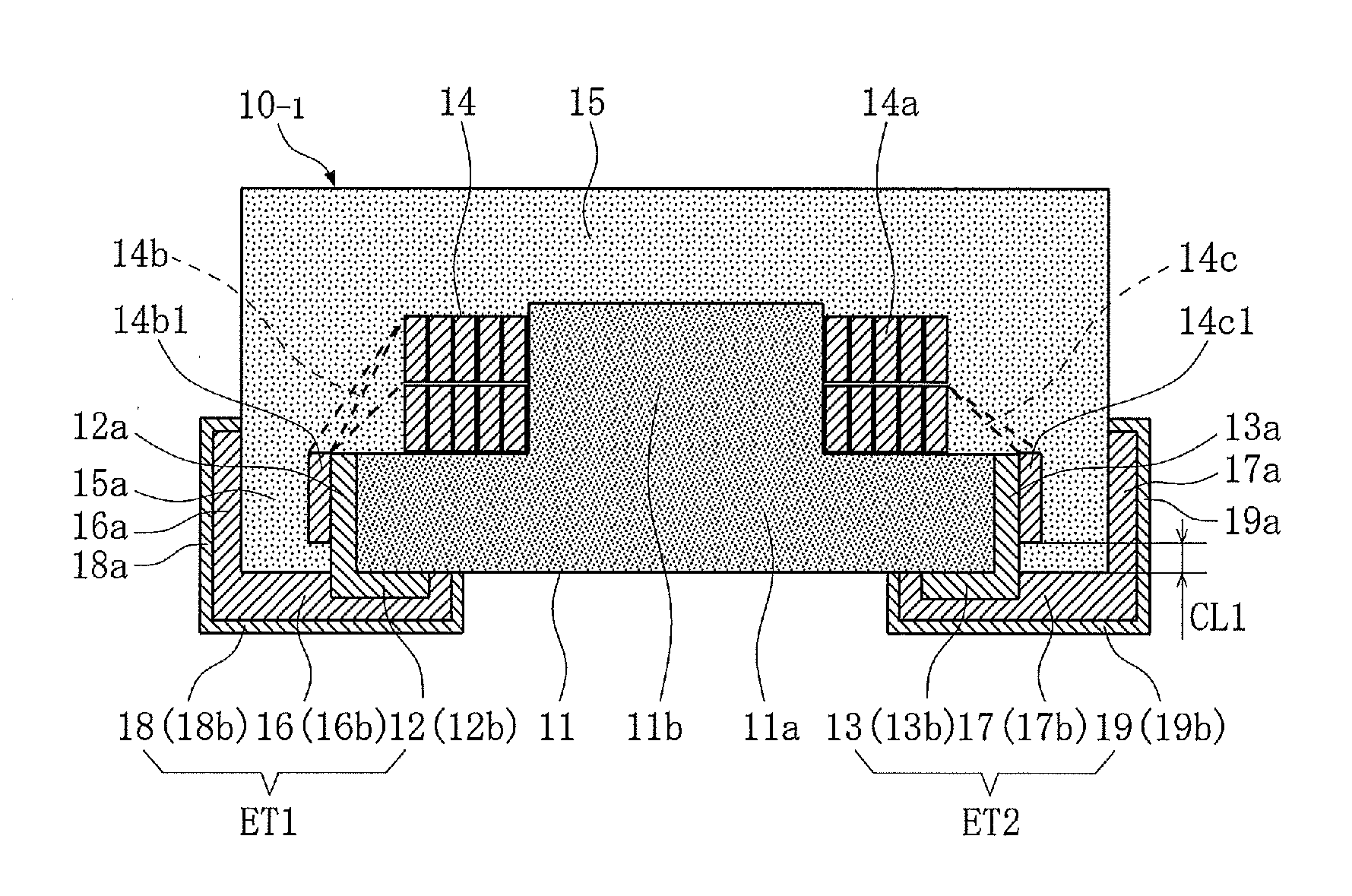
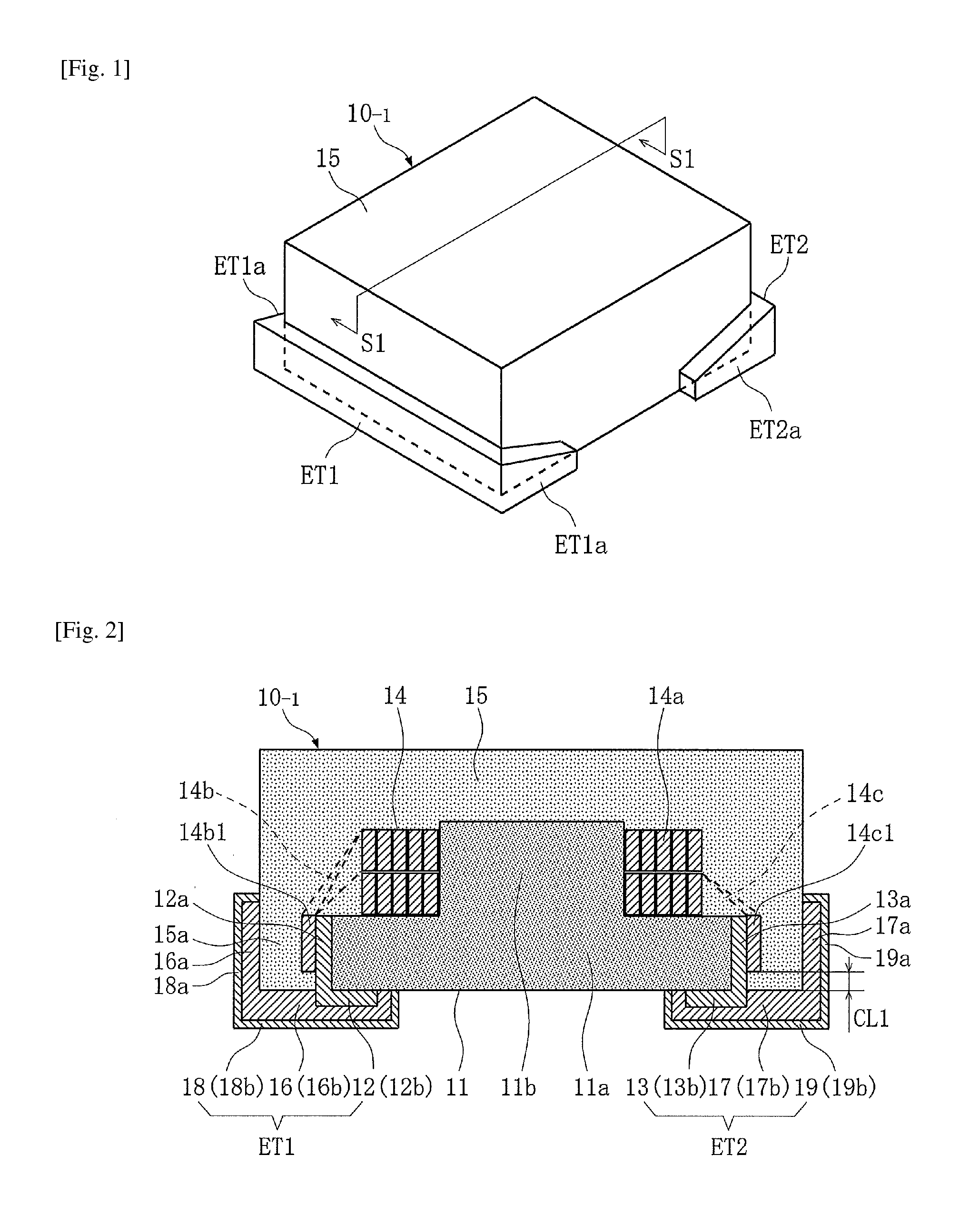
[0042]FIGS. 1 to 4 show a coil component to which the present invention is applied (Embodiment 1). First, FIGS. 1 to 4 are used to explain the constitution of this coil component 10-1. For the purpose of explanation, top, bottom, left, right, front and rear of FIG. 2 are referred to as top, bottom, front, rear, left and right, respectively, and the same applies to the corresponding directions of FIGS. 1 and 3.
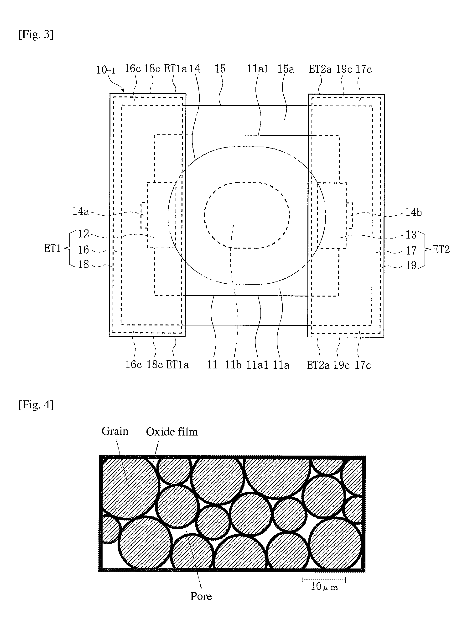
[0043]The coil component 10-1 shown in FIGS. 1 to 3 has a magnetic core 11, a pair of first conductive films 12, 13, a coil 14, a magnetic sheath 15, a pair of second conductive films 16, 17 and a pair of third conductive films 18, 19. The size of this coil component 10-1 is, for example, 2.5 mm in front-rear dimension, 2.0 mm in left-right dimension, and 1.0 mm in top-bottom dimension.
[0044]The magnetic core 11 integrally has a sheet part 11a having a profile, as viewed from the bottom, of a rough rectangle as well as a specific thickness (such as 0.24 mm when the top-bottom d...
embodiment 2
[0070]FIGS. 5 and 6 show a coil component to which the present invention is applied (Embodiment 2). This coil component 10-2 is different from the coil component 10-1 in Embodiment 1 in that:[0071]Along the outer periphery of the bottom face of the sheet part 11a of the magnetic core 11, the two areas 11a1 not covered by the first external terminal ET1 and the second external terminal ET2 are entirely covered by a part 15b extending downward from the part 15a of the magnetic sheath 15 covering the side face of the sheet part 11a of the magnetic core 11.
[0072]The remainder of the constitution is the same as that of the coil component 10-1 in Embodiment 1 and therefore not explained.
[0073]This coil component 10-2 achieves below in addition to to mentioned above.
[0074] By actively and entirely covering, by the downward extension part 15b of the magnetic sheath 15, the two areas 11a1 not covered by the first external terminal ET1 and the second external terminal ET2 along the outer p...
embodiment 3
[0076]FIG. 7 shows a coil component to which the present invention is applied (Embodiment 3). This coil component 10-3 is different from the coil component 10-1 in Embodiment 1 in that:[0077]Along the outer periphery of the bottom face of the sheet part 11a of the magnetic core 11, the two areas 11a1 not covered by the first external terminal ET1 and the second external terminal ET2 are partially (at two locations each) covered by a part 15c extending downward from the part 15a of the magnetic sheath 15 covering the side face of the sheet part 11a of the magnetic core 11.
[0078]The remainder of the constitution is the same as that of the coil component 10-1 in Embodiment 1 and therefore not explained.
[0079]This coil component 10-3 achieves below in addition to to mentioned above.
[0080] By partially (at two locations each) covering, by the downward extension part 15c of the magnetic sheath 15 the two areas 11a1 not covered by the first external terminal ET1 and the second external ...
PUM
 Abstract
Description
Claims
Application Information
 - Generate Ideas
- Intellectual Property
- Life Sciences
- Materials
- Tech Scout
- Unparalleled Data Quality
- Higher Quality Content
- 60% Fewer Hallucinations
Browse by: Latest US Patents, China's latest patents, Technical Efficacy Thesaurus, Application Domain, Technology Topic, Popular Technical Reports.
© 2025 PatSnap. All rights reserved.Legal|Privacy policy|Modern Slavery Act Transparency Statement|Sitemap|About US| Contact US: help@patsnap.com